


DRIVE SYSTEMS
BELT REPLACEMENT
Belt Replacement, Bail System
The belt drive models use one of two systems; the
spring loaded or constant tension system and the
control bail system. Depending on the model you
might see a standard V belt or a wide flat belt with
several V grooves. Note there are two versions of the
multi-groove belt. While they look alike, there is a
difference in width. Use the parts list for your model to
assure you use the correct belt for the application.
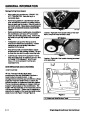
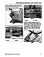
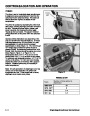
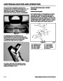
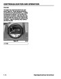
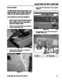
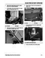
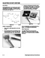
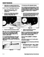
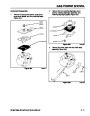
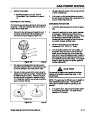
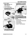
Remove the belt cover (Figure 89).
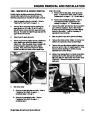
To Replace The Drive Belt On A Constant Tension
System
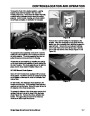
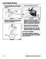
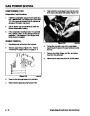
Remove the belt cover on the left hand side of the
machine. Typically there are 5 fasteners holding the
belt cover on. Those in the front near the rotor are
bolts with locknuts. In the rear of the cover, there are
self-tapping screws. With the cover off, the drive
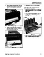
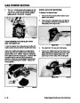
system is exposed. Lift the idler pulley and slide the
belt out towards you. Release tension on the idler
slowly. Then slip the belt off the engine and rotor
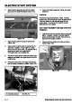
pulleys. With the belt removed, visually inspect the
rotor and engine pulleys for damage or wear and
replace as necessary. Inspect the idler pulley and the
idler arm to ensure free rotation and smooth travel.
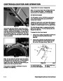
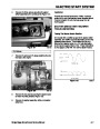
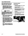
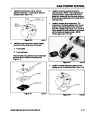
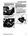
The idler spring has one end hooked into the idler arm
and the other is typically hooked into a notch in the
frame directly below the idler. To install a new belt,
route the belt around the engine and rotor pulleys.
Then pull the idler arm upward and slip the belt under
the pulley. The arm must sit on top of the belt and
push it downward.
Figure 89
1854-04
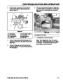
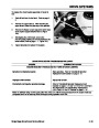
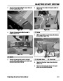
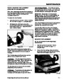
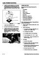
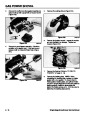
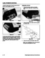
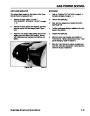
The drive system is now exposed. Pull the idler pulley
up and slip the belt out from under the pulley, release
tension on the idler slowly. Slip the belt off the engine
and rotor pulleys and from under the brake arm
assembly.
B
A
C
D
G
A
F
E
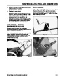
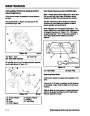
Figure 90
0623-10
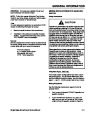
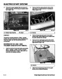
(A) Engine Pulley
(B) Idler Pulley
(C) Brake Spring
(E) Rotor Pulley
(F) Roller
(G) Belt Guide
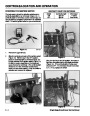
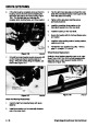
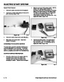
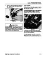
B
C
(D) Brake Arm Assembly
Figure 88
0623-05
Reverse the process to install the new belt. Note the
belt must route under the brake and idler pulley. See
Figure 90.
(
A) Idler Pulley
(C) Notch
(B) Idler Spring
5 - 14
Single Stage Snowthrower Service Manual
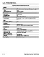
| Categories | Snow Blower Manuals, Toro Snow Blower |
|---|---|
| Tags | Toro 1028 Power Shift, Toro 1332 Power Shift, Toro 38014, Toro 38030, Toro 38079, Toro 38087, Toro 38400, Toro 38405, Toro 38513, Toro 38543, Toro 38558, Toro 38559, Toro 38574, Toro 624, Toro 824, Toro 828, Toro 924, Toro CCR 1000 |
| Model Year | 1978, 1992, 1993, 1994, 1995, 1996, 1997, 1998, 1999, 2000, 2001, 2002, 2003 |
| Download File |
|
| Document Type | Service Manual |
| Language | English |
| Serial Number | 200000001 - 200999999 |
| Product Name | Toro CCR 1000 Snowthrower |
| Product Brand | Toro. Customer Service Representatives are available by phone:
Monday - Friday 7:30 a.m. to 9:00 p.m. (CDT) - Saturday 8:00 a.m. to 8:00 p.m. (CDT) - Sunday 10:00 a.m. to 8:00 p.m. (CDT)
Canada 1-888-225-4886 USA 1-888-384-9939, Snow Blower |
| Product Type | Snowthrower |
| Product Series | CCR 1000/2400/2500, Single Stage, Snowthrower |
| Swath | 20 inch |
| Discharge | Single Stage |
| Engine Manufacturer | Tecumseh |
| Engine Oil Type | Toro 2 cycle / NMMA-TCW3 |
| Engine Motor Model # | HSK635-1721A |
| Engine Motor Size | 3.5 hp |
| Engine Motor Type | 2 Cycle EPA1 |
| Document File Type | |
| Publisher | toro.com |
| Wikipedia's Page | Toro Company |
| Copyright | Attribution Non-commercial |
(0 votes, average: 0 out of 5)