


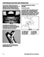


DRIVE SYSTEMS
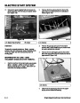
BELT/PULLEY ALIGNMENT
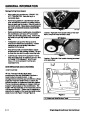
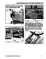
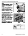
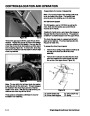
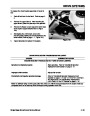
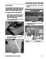
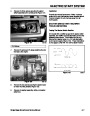
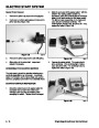
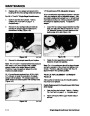
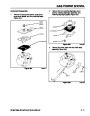
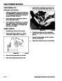
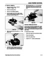
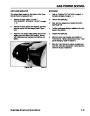
20” CCR models have an engine pulley that is held on
with two set screws. Move the engine pulley in or out
to achieve alignment. Tighten the engine pulley set
screws with the square head screw first, then the hex
head screw (Figure 92). Torque both to 120 -150 in·lbs
(1356 N·cm - 1695 N·cm).
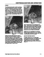
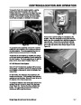
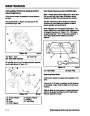
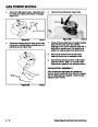
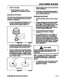
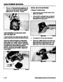
While perfection is not required in this application, the
pulleys should be aligned fairly close. Use a straight
edge long enough to run from the lower end of the rotor
pulley to the upper end of the engine pulley. Applying
the straight edge to the two pulleys will indicate how
close the pulleys are to being in line. Within 1/8” of
alignment will provide good belt life.
A
B
Figure 92
1854-02
(A) Square Head Screw
(B) Hex Head Screw
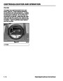
Figure 91
1352-06
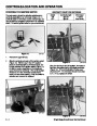
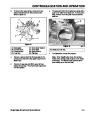
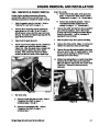
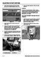
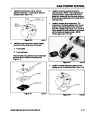
ENGINE PULLEY REPLACEMENT
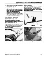
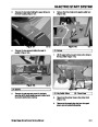
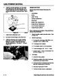
ADJUSTING PULLEY ALIGNMENT
Powerlite Models
Powerlite Models
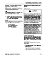
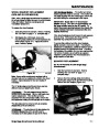
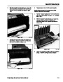
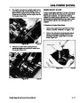
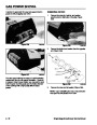
The Powerlite models have the engine pulley keyed to
the crankshaft and retained with one bolt through the
pulley into the end of the crankshaft (Figure 93). The
preferred method of removing this bolt is with an
impact wrench. However, if an impact wrench is not
available, any wrench of the proper size will work. It
will be necessary to hold the crankshaft with a vise grip
or other tool to prevent rotation. When installing the
new pulley, install the key in the crankshaft, slide the
pulley half over the key. Apply blue Loctite to the
screw and secure both pulley halves with the
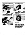
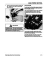
On Powerlite models, neither the rotor or engine
pulleys can be moved inward. However, either pulley
could be shimmed out using spacer washers. Adding a
spacer washer between the hub and rotor pulley or
between the engine pulley and the shoulder on the
crankshaft would shim the pulley outward.
CAUTION: Excessive shimming may cause the
pulley to contact the belt cover. Be sure to test fit
the cover to make sure there is no contact.
capscrew. Follow the steps under "ADJUSTING
PULLEY ALIGNMENT" on page 5 - 15.
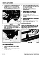
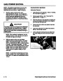
The bolt on the engine pulley and the locknut on the
rotor pulley are both counterclockwise to remove.
Note: If you do not have an impact wrench, it may be
necessary to hold the crankshaft or the rotor in order to
loosen the nut or bolt.
During reassembly torque the engine pulley bolt to 225
in·lbs (2540 ± 280 N·cm) and the rotor pulley to 55 ± 5
ft·lbs (75 ± 7 N·m).
Single Stage Snowthrower Service Manual
5 - 15
| Categories | Snow Blower Manuals, Toro Snow Blower |
|---|---|
| Tags | Toro 1028 Power Shift, Toro 1332 Power Shift, Toro 38014, Toro 38030, Toro 38079, Toro 38087, Toro 38400, Toro 38405, Toro 38513, Toro 38543, Toro 38558, Toro 38559, Toro 38574, Toro 624, Toro 824, Toro 828, Toro 924, Toro CCR 1000 |
| Model Year | 1978, 1992, 1993, 1994, 1995, 1996, 1997, 1998, 1999, 2000, 2001, 2002, 2003 |
| Download File |
|
| Document Type | Service Manual |
| Language | English |
| Serial Number | 200000001 - 200999999 |
| Product Name | Toro CCR 1000 Snowthrower |
| Product Brand | Toro. Customer Service Representatives are available by phone:
Monday - Friday 7:30 a.m. to 9:00 p.m. (CDT) - Saturday 8:00 a.m. to 8:00 p.m. (CDT) - Sunday 10:00 a.m. to 8:00 p.m. (CDT)
Canada 1-888-225-4886 USA 1-888-384-9939, Snow Blower |
| Product Type | Snowthrower |
| Product Series | CCR 1000/2400/2500, Single Stage, Snowthrower |
| Swath | 20 inch |
| Discharge | Single Stage |
| Engine Manufacturer | Tecumseh |
| Engine Oil Type | Toro 2 cycle / NMMA-TCW3 |
| Engine Motor Model # | HSK635-1721A |
| Engine Motor Size | 3.5 hp |
| Engine Motor Type | 2 Cycle EPA1 |
| Document File Type | |
| Publisher | toro.com |
| Wikipedia's Page | Toro Company |
| Copyright | Attribution Non-commercial |
(0 votes, average: 0 out of 5)