

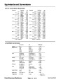
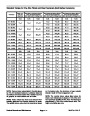


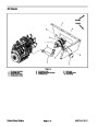
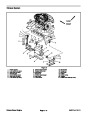
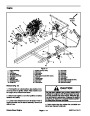


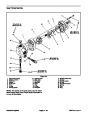

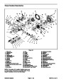
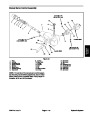
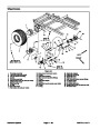


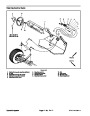
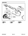


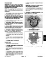

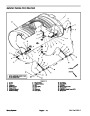
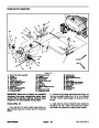
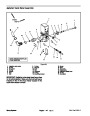


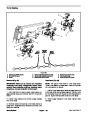
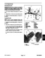
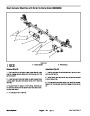
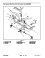
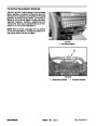


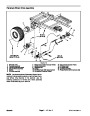
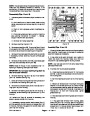


Boom Valve Motor Assembly
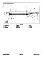
15
14
18
2
1
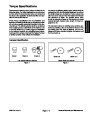
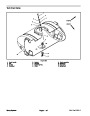
FRONT
RIGHT
17
13
4
16
3
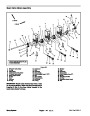
3
2
2
5
2
11
7
2
12
20
2
19
10
8
21
9
7
22
8
16
6
7
7
6
7
8
26
23
8
7
27
24
26
26
28
27
25
29
30
28
29
27
30
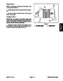
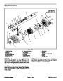
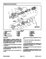
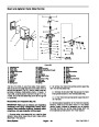
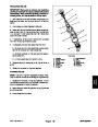
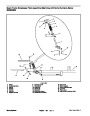
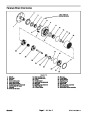
NOTE: ARROWS SHOW FLUID
FLOW DIRECTION
28
29
30
Figure 22
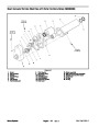
1.
2.
3.
4.
5.
6.
7.
8.
9.
10.
RH boom valve motor
O–ring
11. Connector
12. Fork
21. Washer
22. Rod
Valve joiner
13. Hosebarb
23. Hosebarb
Center boom valve motor
LH boom valve motor
Boom bypass joiner
O–ring
14. Hose clamp
15. Boom supply hose (1 1/2”)
16. Nut
24. Hose clamp
25. Boom bypass hose (1”)
26. Screw
27. Mounting bracket
28. O–ring
29. Hosebarb (boom hose)
30. Nut
17. Tube coupler
18. Pressure tube
19. End cover
Fork
End cap
O–ring
20. O–ring
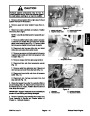
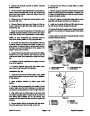
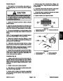
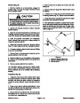
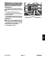
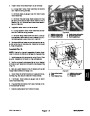
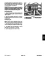
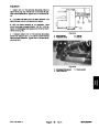
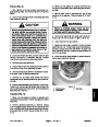
IMPORTANT: Boom valve motors may have a fuse
for circuit protection. Make sure that correct fuse is
installed in the in–line fuse holder located in the
boom valve motor harness.
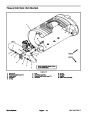
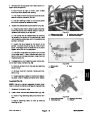
Spray System
Multi Pro 5700–D
Page 6 – 22 Rev. A
| Categories | Lawn Mower Manual, Sprinkler and Irrigation Manuals, Toro Sprinkler and Irrigation Manuals |
|---|---|
| Tags | Toro 5700 D |
| Download File |
|
| Document Type | Catalog |
| Language | English |
| Product Brand | Toro. Customer Service Representatives are available by phone:
Monday - Friday 7:30 a.m. to 9:00 p.m. (CDT) - Saturday 8:00 a.m. to 8:00 p.m. (CDT) - Sunday 10:00 a.m. to 8:00 p.m. (CDT)
Canada 1-888-225-4886 USA 1-888-384-9939, Lawn Mower |
| Document File Type | |
| Publisher | toro.com |
| Wikipedia's Page | Toro Company |
| Copyright | Attribution Non-commercial |
(0 votes, average: 0 out of 5)