


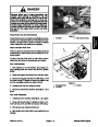


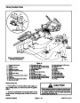
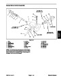
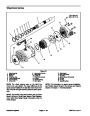


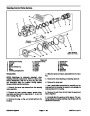


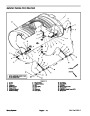
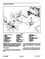
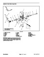
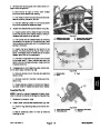


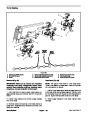
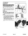
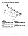
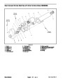
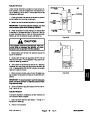


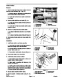


Removal (Fig. 38)
Park machine on a level surface, stop engine, en•
gage parking brake, and remove key from the ignition
switch.
2. If motor hub was removed, apply anti–seize lubricant
to motor shaft. Install woodruff key in shaft and slide hub
onto motor shaft.
1.
3. Position motor on pump mounting bracket and install
flange head screws and flange nuts to motor and mount•
ing bracket. Leave fasteners loose.
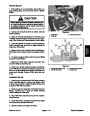
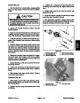
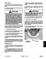
CAUTION
4.
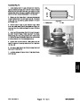
Place coupling spacers into rubber coupling. Install
cap screws, flat washers, and lock nuts to secure rubber
coupling to motor hub. Make sure that cap screw
threads extend through lock nut.
Rotate steering wheel and depress traction ped•
al in both forward and reverse to relieve hydrau•
lic system pressure and to avoid injury from
pressurized hydraulic oil.
5. If motor hub was removed, apply Loctite #242 (or
equivalent) to threads of motor hub set screws. Install
set screws into hub to secure hub to motor shaft.
2.
Operate all hydraulic controls to relieve hydraulic
system pressure.
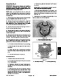
6.
Turn pump shaft by hand and position motor on
mounting bracket to best align the coupling assembly
between the pump shaft and the hydraulic motor shaft.
3.
Installing Hydraulic System Components at the begin•
ning of the Service and Repairs section of this chapter.
Read the General Precautions for Removing and
7.
Secure motor to mounting bracket by tightening
flange head screws and flange nuts.
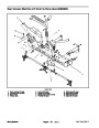
4.
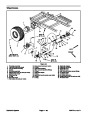
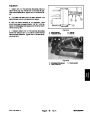
Remove flange head screw and flange nut that se•
cure front and rear guard plate. Remove four (4) flange
nuts that retain guard plates to pump mount bracket. Re•
move guard plates from machine.
8.
correct hydraulic fittings on motor.
Lubricate new o–rings and install hydraulic hoses to
9.
Position front and rear guard plates to pump mount
5.
Clean hydraulic hose ends prior to disconnecting the
hoses from hydraulic motor.
Label all hydraulic connections to ease reassembly.
bracket. Install and tighten flange head screw and
flange nut to guard plates. Install flange nuts to secure
guard plates to pump mount bracket.
6.
to drain into a suitable container.
Disconnect hydraulic hoses from motor. Allow hoses
10.Check
as required (see Operator’s Manual).
fluid level in hydraulic oil reservoir and adjust
7.
to prevent contamination.
Put caps or plugs on disconnected hoses and fittings
11.
System in the Service and Repairs section of this chap•
ter).
Properly fill hydraulic system (see Charge Hydraulic
8.
Remove lock nuts, flat washers, cap screws, and
coupler spacers that secure rubber coupling to hydraulic
motor hub.
12.Stop
hydraulic reservoir oil level.
engine and check for hydraulic oil leaks. Check
9.
Remove two (2) flange head screws and flange nuts
that secure hydraulic motor to pump mount bracket.
10.Remove
hydraulic motor from machine.
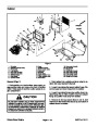
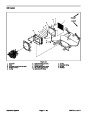
1
11.
If needed, loosen set screws in hydraulic motor hub.
Pull hub from motor shaft. Locate and remove woodruff
key from motor shaft. Remove set screws from hub.
Clean threads of set screws and hub.
3
12.If
hydraulic fitting removal is needed, note orientation
of hydraulic fittings before removing fittings from motor.
2
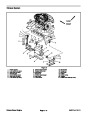
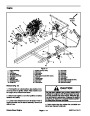
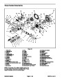
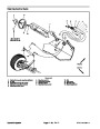
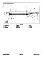
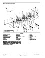
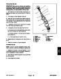
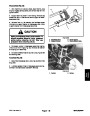
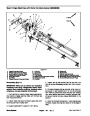
Installation (Fig. 38)
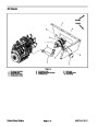
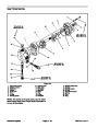
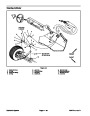
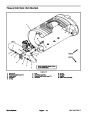
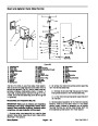
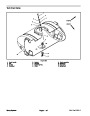
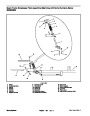
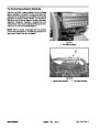
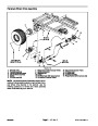
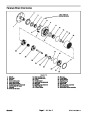
Figure 39
1.
lic fittings to motor.
If removed, lubricate new o–rings and install hydrau•
1.
2.
3.
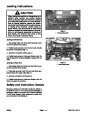
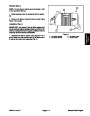
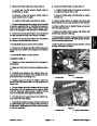
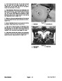
Spray pump drive motor
Hydraulic hose (from PWM CF port)
Hydraulic hose (to PWM EX port)
Multi Pro 5700–D
Page 4 – 43
Hydraulic System
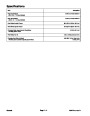
| Categories | Lawn Mower Manual, Sprinkler and Irrigation Manuals, Toro Sprinkler and Irrigation Manuals |
|---|---|
| Tags | Toro 5700 D |
| Download File |
|
| Document Type | Catalog |
| Language | English |
| Product Brand | Toro. Customer Service Representatives are available by phone:
Monday - Friday 7:30 a.m. to 9:00 p.m. (CDT) - Saturday 8:00 a.m. to 8:00 p.m. (CDT) - Sunday 10:00 a.m. to 8:00 p.m. (CDT)
Canada 1-888-225-4886 USA 1-888-384-9939, Lawn Mower |
| Document File Type | |
| Publisher | toro.com |
| Wikipedia's Page | Toro Company |
| Copyright | Attribution Non-commercial |
(0 votes, average: 0 out of 5)