


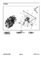
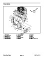
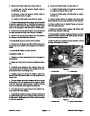
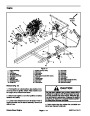


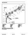

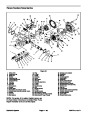
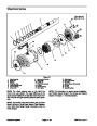


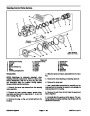
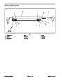
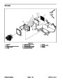


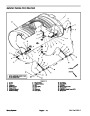
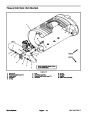
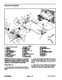
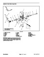
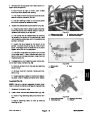


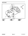
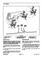
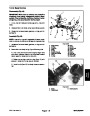
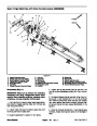
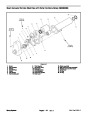
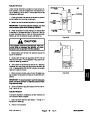


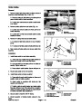
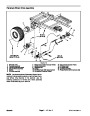
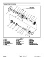


Disassembly (Fig. 4)
Park machine on a level surface, stop engine, en•
gage parking brake, and remove key from the ignition
switch.
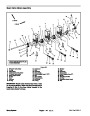
Assembly (Fig. 4)
1.
1. If removed, install bushings and steering stop bolt
into spindle.
2.
Place thrust bearing in top of spindle. Position
spindle to front axle. Slide king pin into front axle and
spindle.
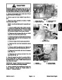
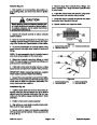
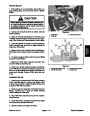
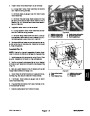
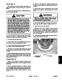
CAUTION
3.
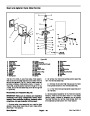
king pin to front axle.
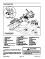
Install washer head screw and flat washer to secure
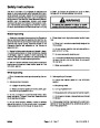
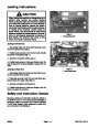
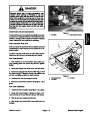
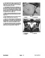
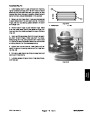
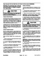
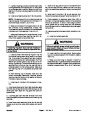
When changing attachments, tires, or perform•
ing other service, use correct blocks, hoists,
and jacks. Make sure machine is parked on a
solid, level surface such as a concrete floor.
Prior to raising machine, remove any attach•
ments that may interfere with the safe and
proper raising of the machine. Always chock or
block wheels. Use jack stands or solid wood
blocks to support the raised machine. If the ma•
chine is not properly supported by blocks or
jack stands, the machine may move or fall,
which may result in personal injury.
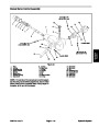
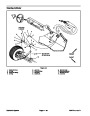
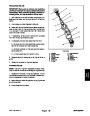
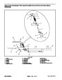
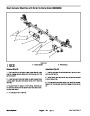
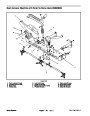
4. If left side spindle was removed, attach hydraulic
steering cylinder to spindle (see Steering Cylinder in
Service and Repairs Section of Chapter 4 – Hydraulic
System).
5. Secure tie rod end to spindle (see Tie Rod End in this
section).
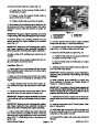
WARNING
2.
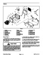
structions in Operator’s Manual).
Jack front of machine off ground (see Jacking In•
Failure to maintain proper lug nut torque
could result in failure or loss of wheel and may
result in personal injury.
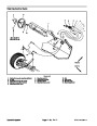
3.
Remove front wheel assembly and wheel hub from
machine (see Front Wheels and Hubs in this section).
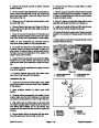
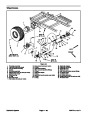
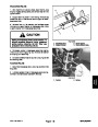
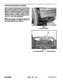
6.
Install wheel with valve stem facing out and secure
with lug nuts. Torque lug nuts evenly in a crossing pat•
tern from 55 to 75 ft–lb (75 to 102 N–m).
4.
in this section).
Remove tie rod end from spindle (see Tie Rod Ends
7.
Operator’s Manual).
Lubricate grease fittings on front axle assembly (see
5.
If left side spindle is being removed, separate hy•
draulic steering cylinder from spindle (see Steering Cyl•
inder in Service and Repairs Section of Chapter 4 –
Hydraulic System).
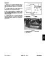
8.
9.
Lower machine to ground.
Check and adjust front wheel toe–in (see Operator’s
6.
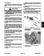
cure king pin to front axle.
Remove washer head screw and flat washer that se•
Manual).
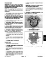
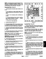
10.Adjust
full turn, there is a 1/16” (1.6 mm) gap between the tie
rod and front axle.
steering stop bolt on each spindle so that at
7.
during disassembly. Slide king pin from front axle and
spindle. Remove spindle from front axle.
Support spindle assembly to prevent it from falling
11.
components do not contact hoses and/or wires.
After assembly is complete, make sure that steering
8.
Remove thrust bearing from top of spindle.
9.
If needed, remove bushings and steering stop bolt
from spindle.
Multi Pro 5700–D
Page 7 – 7
Chassis
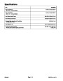
| Categories | Lawn Mower Manual, Sprinkler and Irrigation Manuals, Toro Sprinkler and Irrigation Manuals |
|---|---|
| Tags | Toro 5700 D |
| Download File |
|
| Document Type | Catalog |
| Language | English |
| Product Brand | Toro. Customer Service Representatives are available by phone:
Monday - Friday 7:30 a.m. to 9:00 p.m. (CDT) - Saturday 8:00 a.m. to 8:00 p.m. (CDT) - Sunday 10:00 a.m. to 8:00 p.m. (CDT)
Canada 1-888-225-4886 USA 1-888-384-9939, Lawn Mower |
| Document File Type | |
| Publisher | toro.com |
| Wikipedia's Page | Toro Company |
| Copyright | Attribution Non-commercial |
(0 votes, average: 0 out of 5)