


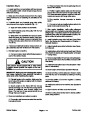

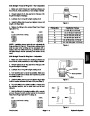
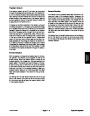
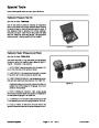


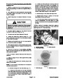
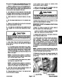
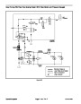
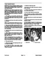
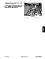

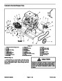
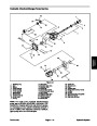
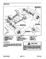


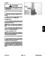


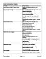
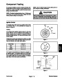
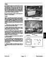
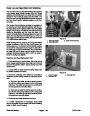

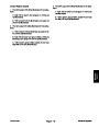
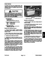
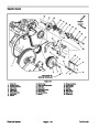

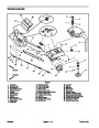


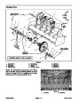


Head Low and Head High Limit Switches
The head low and head high limit switches are attached
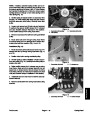
to the coring depth control housing (Fig. 25). These
switches are normally open and close when the switch
actuator in the housing is rotated past the switch. The
head low and head high limit switches provide inputs for
3
the True Core
Core 648.
TM
ground following system on the Pro-
1
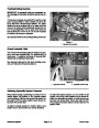
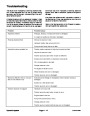
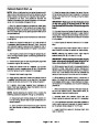
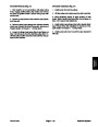
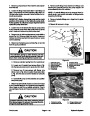
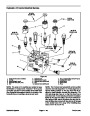
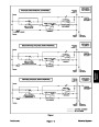
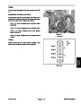
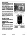
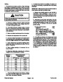
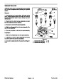
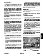
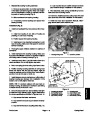
The Aerator Control Module monitors the operation of
the head low and head high limit switches. With the cor•
ing head raised and the ignition switch in the ON position
(engine not running), the Module head high input LED
should be illuminated and the head low input LED
should not be illuminated. By slowly raising the outer turf
guard, the head high input LED should go out. If the out•
er turf guard continues to be raised, the head low input
LED will illuminate slightly later.
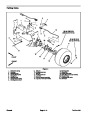
2
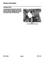
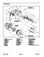
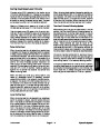
Figure 25
1.
2.
Head high switch
Head low switch
3.
Depth control housing
While aerating with the ProCore, the turf guards follow
surface undulations. With the True Core
TM
ground fol•
lowing system on, the Aerator Control Module receives
an input if the turf guards move enough to close either
the head high or head low limit switch. The Control Mod•
ule uses that input to allow a current output to the ap•
propriate hydraulic solenoid (SVR or SVL) to raise or
lower the coring head slightly.
2
3
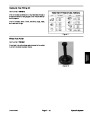
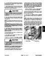
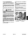
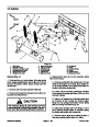
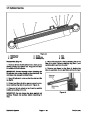
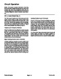
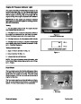
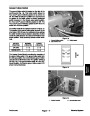
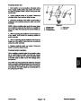
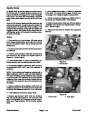
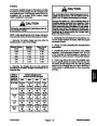
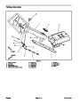
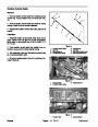
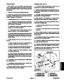
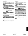
Head Low and Head High Switch Test
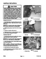
1.
Park machine on a level surface, fully raise coring
head, engage parking brake, stop engine and remove
key from the ignition switch. Secure coring head with
service latch.
1
2.
Locate switch on depth control housing. Disconnect
the switch electrical connector.
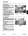
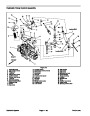
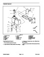
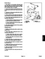
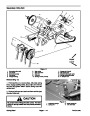
Figure 26
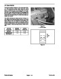
3.
multimeter (ohms setting) across the connector termi•
nals.
Check the continuity of the switch by connecting a
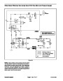
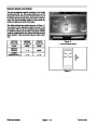
1.
2.
Control module
Head low LED
3.
Head high LED
A. The head high switch should be closed (continu•
ity) with the coring head raised and the turf guards
extended. The switch should open (no continuity) if
the turf guards are manually raised.
B. The head low switch should be open (no continu•
ity) with the coring head raised and the turf guards
extended. The switch should close (continuity) if the
turf guards are manually raised.
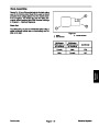
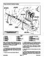
4.
5.
Reconnect the switch electrical connector.
If switch replacement is necessary, apply small
amount of grease onto the switch ball before installing
switch in depth control housing.
Electrical System
ProCore 648
Page 5 – 20
| Categories | Lawn Mower Manual, Sprinkler and Irrigation Manuals, Toro Sprinkler and Irrigation Manuals |
|---|---|
| Tags | Toro 648 |
| Download File |
|
| Document Type | Service Manual |
| Language | English |
| Product Brand | Toro. Customer Service Representatives are available by phone:
Monday - Friday 7:30 a.m. to 9:00 p.m. (CDT) - Saturday 8:00 a.m. to 8:00 p.m. (CDT) - Sunday 10:00 a.m. to 8:00 p.m. (CDT)
Canada 1-888-225-4886 USA 1-888-384-9939, Lawn Mower |
| Document File Type | |
| Publisher | toro.com |
| Wikipedia's Page | Toro Company |
| Copyright | Attribution Non-commercial |
(0 votes, average: 0 out of 5)