


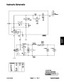
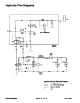


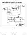
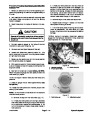


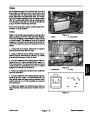
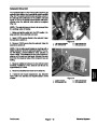

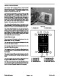

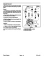


Coring Head Raise/Lower Circuits
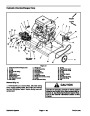
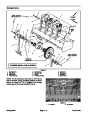
The gear pump (P2) is attached to the traction pump
(P1) and is directly coupled to it. The gear pump supplies
hydraulic flow for maintaining charge pressure of 40 PSI
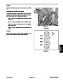
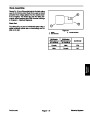
When the coring head reaches the aerating position, so-
lenoid valves SVQ and SVL in the hydraulic manifold are
de–energized. The valve shift of SVQ removes the by-
pass to orifice (ORF1). The valve shift of SVL prevents
oil flow from the lift cylinder. Without flow from the lift cyl-
inder, the cylinder and coring head are held in place.
(2.8
Bar) to the low pressure side of the traction circuit
and also for raising the aerator coring head. The gear
pump takes its suction from the hydraulic reservoir.
Maximum lift/lower circuit pressure is limited to 1000
PSI (69 Bar) by relief valve R1 in the lift control manifold.
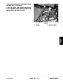
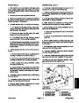
True Core
TM
Ground Following System
When aerating with the ground follow switch in the ON
Flow from gear pump (P2) goes to the lift control man-
ifold (port P) and is directed to pressure compensating
valve (PV). Valve PV ensures that sufficient hydraulic
flow is always available to the traction circuit for charge
oil. When not raising the coring head, gear pump flow in
excess of charge circuit needs is directed to the hydrau-
lic oil filter and then returns to the hydraulic reservoir.
position, the True Core Ground Following System hy-
TM
draulically adjusts the coring head position to ensure
aerating depth consistency over undulating surfaces.
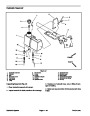
The head high limit and head low limit switches on the
depth actuator assembly are opened or closed depend-
ing on movement of the turf guards over ground irregu-
larities. These switches are used as inputs for the
aerator control module to energize or de–energize sole-
noid valves SVR and SVL in the hydraulic manifold. As
these solenoid valves are energized or de–energized,
the coring head is raised or lowered as described above.
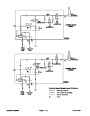
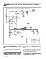
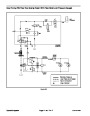
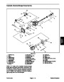
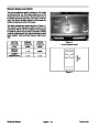
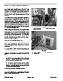
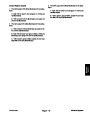
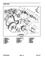
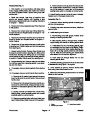
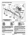
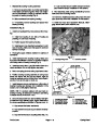
Raise Coring Head
When the coring head is to be raised (e.g. traction lever
is released from forward or raise/lower switch is pressed
to raise), solenoid valves SVR and SVQ in the hydraulic
manifold are energized. The valve shift of SVR prevents
gear pump flow return to the reservoir. The valve shift of
SVQ allows oil flow to bypass the control manifold orifice
(ORF1) for more immediate cylinder movement. Oil
flows through the load holding check valve in solenoid
valve SVL to direct gear pump flow out of control man-
ifold port CYL to the lift cylinder. Hydraulic pressure
against the lift cylinder rod extends the cylinder and
raises the coring head.
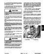
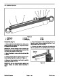
The control manifold orifice (ORF1) restricts oil flow to
and from the lift cylinder to allow more accurate ground
following. Solenoid valve SVQ is always de–energized
when coring head is in the lowered, aerating position.
If the ground follow switch is turned to the OFF position,
the coring head lowers to the manual coring head stops
and the ground following operation is not functional. So-
lenoid valve SVL is always energized while aerating
when the ground follow switch is in the OFF position.
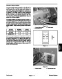
When the raise input ends (e.g. coring head is fully
raised or raise/lower switch is released), solenoid
valves SVR and SVQ in the hydraulic manifold are de–
energized. The valve shift of SVR allows flow return to
the reservoir. The valve shift of SVQ removes the by-
pass to orifice (ORF1). The load holding check valve in
solenoid valve SVL prevents oil flow from the lift cylinder.
Without flow to or from the lift cylinder, the cylinder and
coring head positions are held in place.
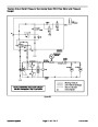
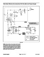
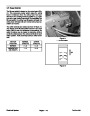
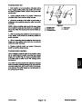
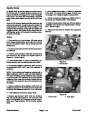
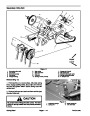
Lower Coring Head
When the coring head is to be lowered (e.g. raise/lower
switch is pressed to lower), solenoid valves SVQ and
SVL in the hydraulic manifold are energized. The valve
shift of SVQ allows oil flow to bypass the control man-
ifold orifice (ORF1) for more immediate cylinder move-
ment. The valve shift of SVL allows a path for oil flow
from the lift cylinder. The weight of the coring head and
tension of the weight transfer springs cause the lift cylin-
der to retract and the coring head to lower. Oil flowing
from the retracting lift cylinder returns to the reservoir.
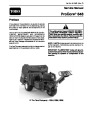
ProCore 648
Page 4 – 11
Hydraulic System
| Categories | Lawn Mower Manual, Sprinkler and Irrigation Manuals, Toro Sprinkler and Irrigation Manuals |
|---|---|
| Tags | Toro 648 |
| Download File |
|
| Document Type | Service Manual |
| Language | English |
| Product Brand | Toro. Customer Service Representatives are available by phone:
Monday - Friday 7:30 a.m. to 9:00 p.m. (CDT) - Saturday 8:00 a.m. to 8:00 p.m. (CDT) - Sunday 10:00 a.m. to 8:00 p.m. (CDT)
Canada 1-888-225-4886 USA 1-888-384-9939, Lawn Mower |
| Document File Type | |
| Publisher | toro.com |
| Wikipedia's Page | Toro Company |
| Copyright | Attribution Non-commercial |
(0 votes, average: 0 out of 5)