

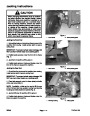


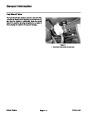


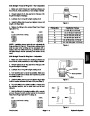
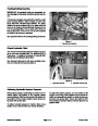


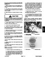
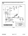
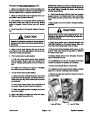
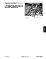

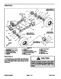


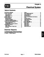
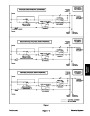


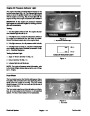
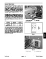

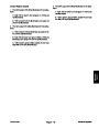
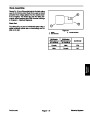

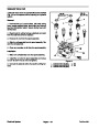

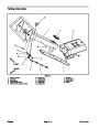
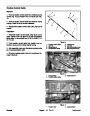


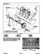
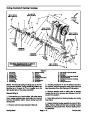
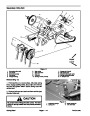


NOTE: Jackshaft rotates counterclockwise as viewed
from right side of machine (Fig. 18).
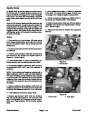
10.Install primary and secondary drive belts to jackshaft
pulleys (see Primary Drive Belt Installation and Secon•
dary Drive Belt Installation in this section).
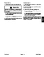
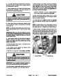
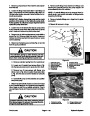
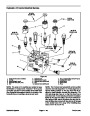
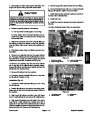
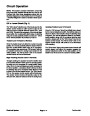
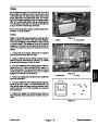
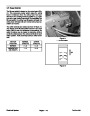
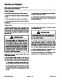
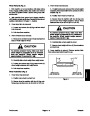
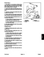
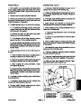
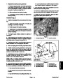
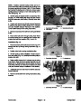
7.
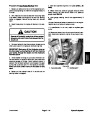
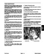
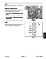
Loosen set screw that secures each flange mount
bearing locking collar to jackshaft. Using the blind hole
in bearing collar as a striking point, unlock collar from
jackshaft by rotating the collar in the opposite direction
of jackshaft rotation with a punch (Fig. 19).
11.Check that belt alignment is still correct. If needed,
readjust pulley location on jackshaft.
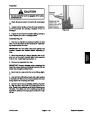
12.Install
belt cover and rear hood to machine (see Op-
erator’s Manual). Remove service latch from coring
head before using machine.
8.
Slide flange mount bearings from jackshaft.
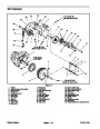
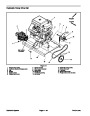
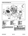
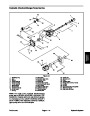
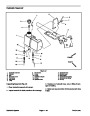
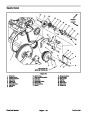
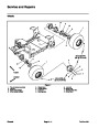
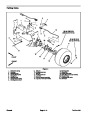
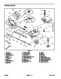
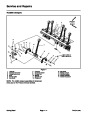
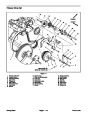
Installation (Fig. 17)
Make sure that tapered surfaces of pulleys and taper
1.
lock bushings are thoroughly clean (no oil, grease, dirt,
rust, etc.).
2.
Slide flange mount bearings onto jackshaft.
3
1
3.
Place woodruff keys (item 6) in jackshaft. Slide pul•
leys and taper lock bushings onto jackshaft making sure
that tapered surfaces of pulley and bushing align. Align
threaded holes of pulley with non–threaded holes of
bushing. Loosely install three (3) cap screws with lock
washers to both bushing and pulley assemblies.
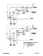
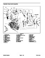
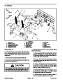
ROTATION
DIRECTION
2
Figure 18
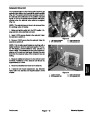
1.
2.
Cap screw/lock washer
Threaded hole
3.
Set screw
4.
cure flange mount bearings to frame with cap screws
and lock nuts.
Position jackshaft assembly to machine frame. Se•
1
IMPORTANT: When tightening bushing cap screws,
tighten in three equal steps and in a circular pattern
to prevent bushing flange damage.
2
5.
Align taper lock bushing in primary pulley flush with
end of jackshaft and secure with set screw. Tighten
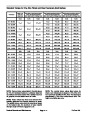
three (3) cap screws to a torque from 180 to 200 in–lb
(20.3
to 22.6 N–m) in three equal steps and in a circular
pattern to secure primary pulley and taper lock bushing.
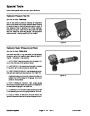
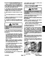
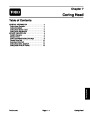
LOOSEN
6.
Position jackshaft to align primary pulley and electric
clutch pulley on engine.
Figure 19
1.
Flange mount bearing
2.
Jackshaft
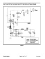
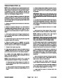
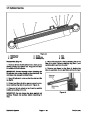
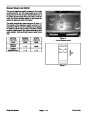
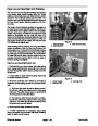
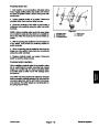
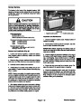
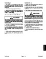
7.
Using the blind hole in flange mount bearing locking
collars as a striking point, lock collars to jackshaft by ro•
tating the collars with a punch in the direction of jack•
shaft rotation (Fig. 20). Tighten set screw (item 11) to
secure each bearing locking collar to jackshaft.
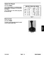
TIGHTEN
2
8.
Position secondary pulley on jackshaft to align sec•
ondary pulley and coring head pulley. Secure in position
with taper lock bushing set screw.
IMPORTANT: When tightening bushing cap screws,
tighten in three equal steps and in a circular pattern.
1
9.
Secure taper lock bushing by tightening three (3) cap
3
screws to a torque from 180 to 200 in–lb (20.3 to 22.6
N–m) in three equal steps and in a circular pattern to se•
cure secondary pulley and taper lock bushing.
Figure 20
1.
2.
Flange mount bearing
Jackshaft
3. Set screw
ProCore 648
Page 7 – 15
Coring Head
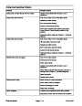
| Categories | Lawn Mower Manual, Sprinkler and Irrigation Manuals, Toro Sprinkler and Irrigation Manuals |
|---|---|
| Tags | Toro 648 |
| Download File |
|
| Document Type | Service Manual |
| Language | English |
| Product Brand | Toro. Customer Service Representatives are available by phone:
Monday - Friday 7:30 a.m. to 9:00 p.m. (CDT) - Saturday 8:00 a.m. to 8:00 p.m. (CDT) - Sunday 10:00 a.m. to 8:00 p.m. (CDT)
Canada 1-888-225-4886 USA 1-888-384-9939, Lawn Mower |
| Document File Type | |
| Publisher | toro.com |
| Wikipedia's Page | Toro Company |
| Copyright | Attribution Non-commercial |
(0 votes, average: 0 out of 5)