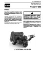


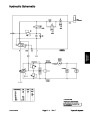
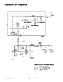


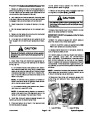


Circuit Operation
NOTE: This section provides information concerning
three sequential, electrical circuits that are used on the
ProCore 648. Use these descriptions along with the
electrical diagrams and schematics found in Chapter 8
–
Electrical Diagrams to better understand circuit opera•
tion.
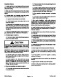
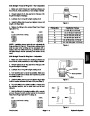
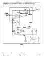
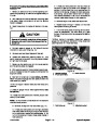
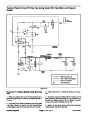
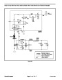
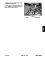
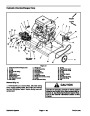
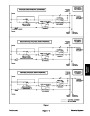
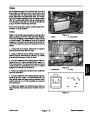
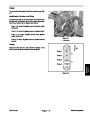
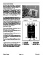
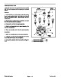
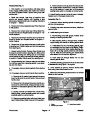
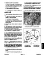
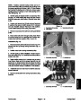
OK to Lower Circuit (Fig. 1)
The ”OK to lower” circuit is one of the inputs used by the
aerator control module to allow current output to the
raise and lower hydraulic solenoid valves (SVL, SVR
and SVQ). This circuit is composed of the manual raise/
lower switch, the neutral switch (latch) relay, the latching
relay, the reverse proximity switch and diode D1. ”OK to
lower” circuit protection is provided by fuse F3.
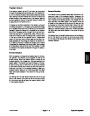
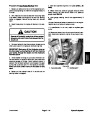
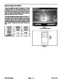
Aerating (Traction Lever in Forward)
Once the ”OK to lower” circuit has initially been closed
by the manual raise/lower switch, the latching relay and
diode D1 allow a latch circuit to keep the latching relay
energized. The manual raise/lower switch in the middle,
aerate position along with the energized latching relay
provide a closed path for the ”OK to lower” input to the
aerator control module. The ”OK to lower” LED on the
aerator control module will continue to be illuminated
while aerating.
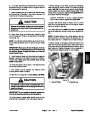
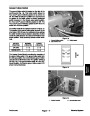
Traction Lever in Neutral or Reverse
When the traction lever is in either the neutral or reverse
position, the reverse proximity switch is closed which al•
lows the neutral switch (latch) relay to be energized.
This energized relay prevents an ”OK to lower” input for
the aerator control so the coring head remains in the
raised position. The ”OK to lower” LED on the aerator
control module will not be illuminated.
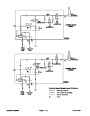
The ”OK to lower” input to the aerator control module will
remain closed until either the operator presses the
manual raise/lower switch to the raise position or the
traction lever is moved to the neutral or reverse position.
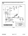
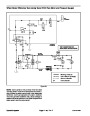
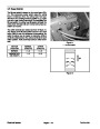
Begin Aerating (Traction Lever in Forward)
To begin aerating, the operator moves the traction lever
to the forward direction which opens the reverse proxim•
ity switch and de–energizes the neutral switch (latch)
relay. When the manual raise/lower switch is pressed to
the lower position, a complete circuit is formed to allow
the latching relay to be energized which allows an ”OK
to lower” input for the aerator control. The ”OK to lower”
LED on the aerator control module will be illuminated.
The aerator control module will provide output to the
SVQ and SVL solenoid valves to lower the coring head.
Electrical System
ProCore 648
Page 5 – 2
| Categories | Lawn Mower Manual, Sprinkler and Irrigation Manuals, Toro Sprinkler and Irrigation Manuals |
|---|---|
| Tags | Toro 648 |
| Download File |
|
| Document Type | Service Manual |
| Language | English |
| Product Brand | Toro. Customer Service Representatives are available by phone:
Monday - Friday 7:30 a.m. to 9:00 p.m. (CDT) - Saturday 8:00 a.m. to 8:00 p.m. (CDT) - Sunday 10:00 a.m. to 8:00 p.m. (CDT)
Canada 1-888-225-4886 USA 1-888-384-9939, Lawn Mower |
| Document File Type | |
| Publisher | toro.com |
| Wikipedia's Page | Toro Company |
| Copyright | Attribution Non-commercial |
(0 votes, average: 0 out of 5)