

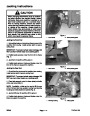


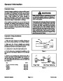
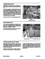


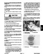
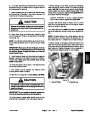
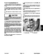
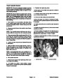

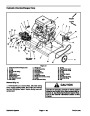
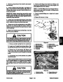
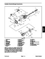


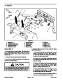


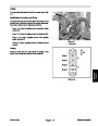

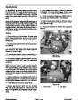

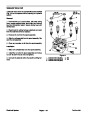


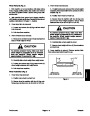
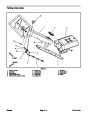
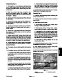


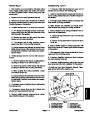
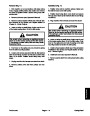


Removal (Fig. 38)
Park machine on a level surface, fully raise coring
3. Remove caps or plugs that were put on any hydraulic
lines or fittings during disassembly.
1.
head, engage parking brake, stop engine and remove
key from the ignition switch. Secure coring head with
service latch.
4. Lightly oil new o–rings for hydraulic fitting and hose
locations.
5.
Correctly connect hydraulic fittings and lines to the
manifold. Tighten all hydraulic fittings and connections.
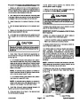
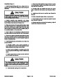
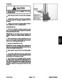
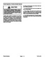
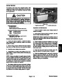
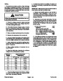
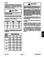
CAUTION
6.
Secure hydraulic manifold by tightening two (2) cap
screws and flange nuts.
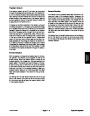
Operate all hydraulic controls to relieve system
pressure and avoid injury from pressurized hy-
draulic oil. See Relieving Hydraulic System Pres-
sure in the General Information section of this
chapter.
7.
8.
Reconnect solenoid valve electrical connectors.
Follow Hydraulic System Start–up procedures.
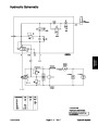
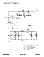
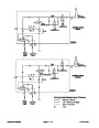
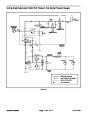
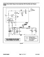
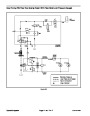
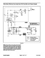
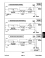
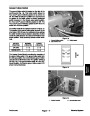
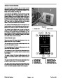
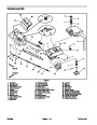
NOTE: The ports on the manifold are marked for easy
identification of components. Example: P is the pump
connection port and R1 is the location for the relief valve
(See Hydraulic Schematic to identify the function of the
hydraulic lines and cartridge valves at each manifold
port location).
11
10
12
13
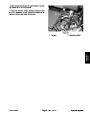
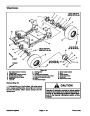
2.
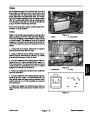
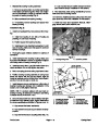
Disconnect solenoid valve electrical connectors.
2
3
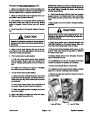
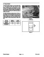
NOTE: The hydraulic reservoir will drain when the hy-
draulic oil filter is removed from the hydraulic manifold.
4
3.
Clean area around hydraulic filter mounting area.
9
Remove filter from hydraulic manifold and drain reser-
voir into a suitable container. Discard filter.
5
6
1
7
2
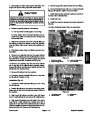
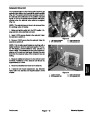
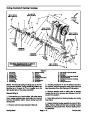
4.
nect hydraulic lines. Label all connections for assembly.
Clean manifold and hydraulic connections. Discon-
3
8
4
5.
Allow hydraulic lines to drain into a suitable contain-
er. Put caps or plugs on disconnected hoses and fittings
to prevent contamination. Discard any removed o–
rings.
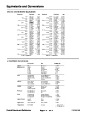
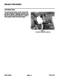
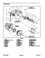
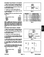
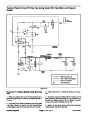
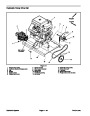
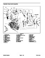
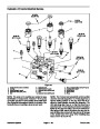
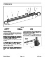
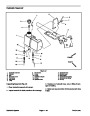
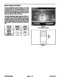
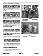
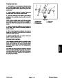
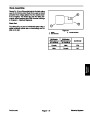
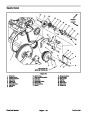
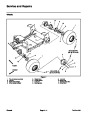
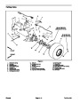
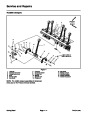
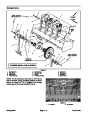
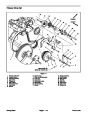
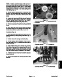
Figure 39
1.
2.
3.
4.
5.
6.
7.
Hydraulic manifold
O–ring
Hydraulic fitting
O–ring
O–ring
Hydraulic fitting
O–ring
8.
9.
10. Hydraulic oil filter
11. Dust cap (2 used)
12. Quick fitting (2 used)
13. O–ring (2 used)
Barbed fitting
O–ring
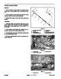
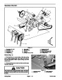
6.
Remove two (2) cap screws and flange nuts that se-
cure hydraulic manifold to the frame mounting bracket.
7.
8.
Remove hydraulic manifold from the machine.
Remove hydraulic fittings from manifold as needed
(Fig. 39).
Installation (Fig. 38)
1.
Position hydraulic manifold to the frame mounting
bracket. Install two (2) cap screws and flange nuts but
do not tighten.
2.
Make sure all hydraulic connections, ports and fit-
tings are clean.
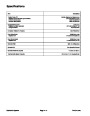
ProCore 648
Page 4 – 47
Hydraulic System
| Categories | Lawn Mower Manual, Sprinkler and Irrigation Manuals, Toro Sprinkler and Irrigation Manuals |
|---|---|
| Tags | Toro 648 |
| Download File |
|
| Document Type | Service Manual |
| Language | English |
| Product Brand | Toro. Customer Service Representatives are available by phone:
Monday - Friday 7:30 a.m. to 9:00 p.m. (CDT) - Saturday 8:00 a.m. to 8:00 p.m. (CDT) - Sunday 10:00 a.m. to 8:00 p.m. (CDT)
Canada 1-888-225-4886 USA 1-888-384-9939, Lawn Mower |
| Document File Type | |
| Publisher | toro.com |
| Wikipedia's Page | Toro Company |
| Copyright | Attribution Non-commercial |
(0 votes, average: 0 out of 5)