


2.
in Service and Repairs section of Chapter 6 – Chassis).
Remove wheel from machine (see Wheel Removal
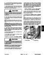
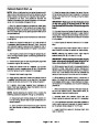
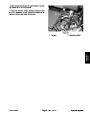
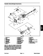
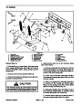
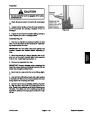
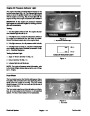
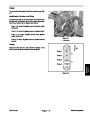
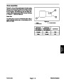
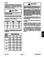
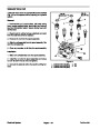
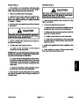
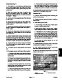
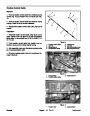
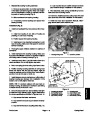
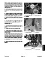
3. If rear wheel motor was removed, slide parking latch
link through parking latch bar and secure with hair pin
(Fig. 36).
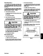
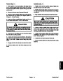
IMPORTANT: To prevent damage to hydraulic motor,
DO NOT hit wheel hub or motor with a hammer dur-
ing wheel hub removal or installation.
4. Remove caps or plugs that were put on any hydraulic
lines or fittings during disassembly.
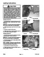
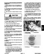
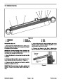
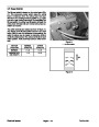
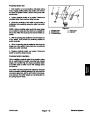
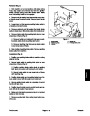
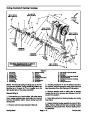
3.
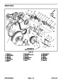
Loosen nut that secures wheel hub to motor shaft.
5. Install hydraulic lines to hydraulic fittings on wheel
motor. Tighten connections.
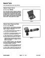
Use wheel hub puller (see Special Tools) to free wheel
hub assembly from motor shaft. Remove nut and hub
assembly from motor shaft. Locate and retrieve wood-
ruff key from motor shaft.
6.
Make sure that wheel motor shaft and wheel hub ta-
per are thoroughly cleaned.
7.
Install woodruff key into motor shaft keyslot. Slide
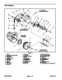
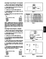
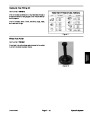
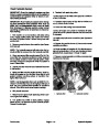
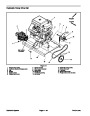
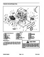
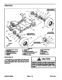
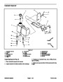
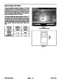
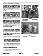
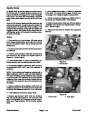
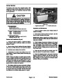
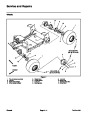
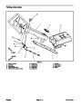
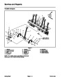
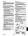
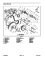
A. Front wheel hub assembly includes wheel hub,
bearing plate and wheel studs.
wheel hub assembly onto motor shaft. Secure wheel
hub to motor shaft with nut. Torque nut from 190 to 230
ft–lbs (258 to 312 N–m).
B. Rear wheel hub assembly includes wheel hub,
bearing plate, parking latch disc and wheel studs.
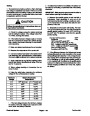
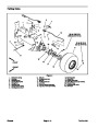
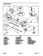
A. Front hub assembly includes wheel hub, bearing
plate and wheel studs.
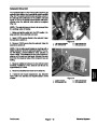
4.
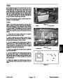
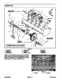
Clean wheel motor and hydraulic connections. Label
hydraulic lines for assembly purposes.
B. Rear hub assembly includes wheel hub, bearing
plate, parking latch disc and wheel studs.
5.
Disconnect hydraulic lines from hydraulic fittings on
motor to be removed. Allow hydraulic oil to drain from
lines into a suitable container. Put caps or plugs on open
hydraulic lines and fittings to prevent contamination.
8.
Service and Repairs section of Chapter 6 – Chassis).
Tighten lug nuts from 45 to 55 ft–lb (61 to 75 N–m).
Install wheel to machine (see Wheel Installation in
6.
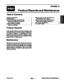
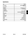
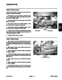
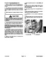
If rear wheel motor is being removed, pull hair pin
that secures parking latch link to parking latch bar (Fig.
Slide link from bar and position link away from park-
ing latch support.
9.
Follow Hydraulic System Start–up procedures.
36).
7.
Support wheel motor. Remove four (4) cap screws
and lock nuts that secure motor to frame. If rear wheel
motor is being removed, remove parking latch support
and parking latch bar. Pull wheel motor from the ma-
chine.
1
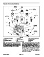
NOTE: If hydraulic fittings are to be removed from
wheel motor, note correct orientation of fittings before
loosening the fittings.
2
8.
If required, remove hydraulic fittings and o–rings
from the wheel motor. Discard o–rings.
3
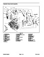
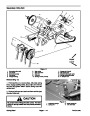
Installation (Fig. 35)
4
1.
If removed, install hydraulic fittings with new o–rings
into the wheel motor. Orientate the fittings as noted dur-
ing disassembly.
5
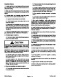
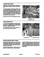
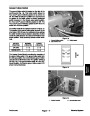
Figure 36
2.
Position and support wheel motor to the frame.
1.
2.
3.
Parking latch link
Hair pin
Parking latch bar
4.
5.
Parking latch support
Wheel motor shaft
A. On front wheel motor, insert four (4) cap screws
through front fork holes and then through motor
flange. Secure motor to front fork with lock nuts.
B. On rear wheel motor, insert four (4) cap screws
through holes in parking latch support (with parking
latch bar installed) and then through motor flange
and frame. Secure motor to frame with lock nuts.
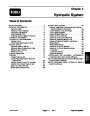
ProCore 648
Page 4 – 43
Hydraulic System
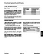
| Categories | Lawn Mower Manual, Sprinkler and Irrigation Manuals, Toro Sprinkler and Irrigation Manuals |
|---|---|
| Tags | Toro 648 |
| Download File |
|
| Document Type | Service Manual |
| Language | English |
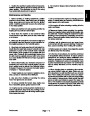
| Product Brand | Toro. Customer Service Representatives are available by phone:
Monday - Friday 7:30 a.m. to 9:00 p.m. (CDT) - Saturday 8:00 a.m. to 8:00 p.m. (CDT) - Sunday 10:00 a.m. to 8:00 p.m. (CDT)
Canada 1-888-225-4886 USA 1-888-384-9939, Lawn Mower |
| Document File Type | |
| Publisher | toro.com |
| Wikipedia's Page | Toro Company |
| Copyright | Attribution Non-commercial |
(0 votes, average: 0 out of 5)