


2.
tor’s Manual).
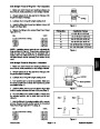
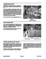
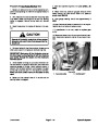
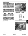
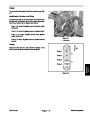
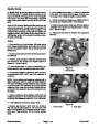
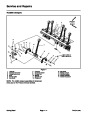
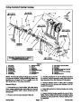
Remove pump belt cover from machine (see Opera-
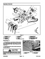
8. Remove both flange head screws and flange nuts
securing the hydraulic pump to the pump support. Lift
pump assembly from the machine.
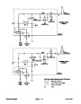
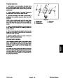
3.
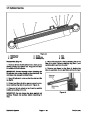
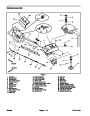
Loosen the flange head screw (item 7) and flange nut
(item 11) that secure the drive belt idler pulley (item 10).
Lift idler pulley to allow removal of drive belt from the hy-
draulic pump pulley.
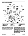
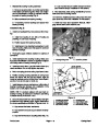
NOTE: If hydraulic fittings are to be removed from hy-
draulic pump, note correct orientation of fittings before
loosening the fittings.
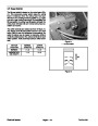
IMPORTANT: Before loosening pump pulley, mark
position of the pulley on the hydraulic pump shaft.
Pulley position is critical for proper alignment of the
hydraulic pump drive belt.
9. Remove hydraulic fittings and o–rings from the pump
as required.
10.Discard
all removed o–rings.
4.
to the hydraulic pump shaft. Slide pulley from the pump
shaft. Locate and remove key from pump shaft.
Loosen two (2) set screws that secure pump pulley
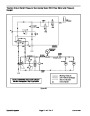
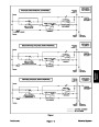
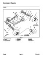
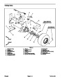
7
11
10
10
8
9
6
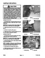
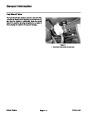
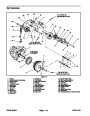
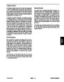
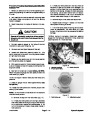
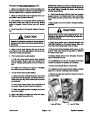
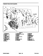
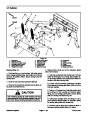
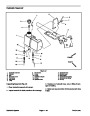
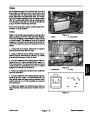
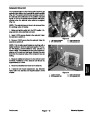
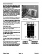
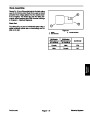
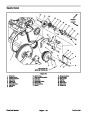
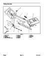
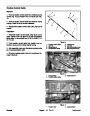
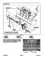
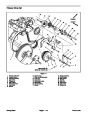
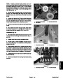
5.
Remove two (2) lock nuts that secure pump shield to
5
pump (Fig. 32). Remove shield from pump. Locate and
retrieve two (2) flat washers from tops of studs on pump
control assembly.
4
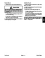
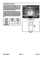
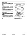
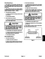
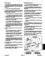
6.
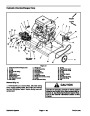
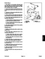
Disconnect hydraulic pump controls (Fig. 32 and 33)
from the pump as follows:
1
3
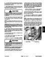
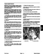
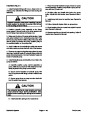
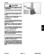
CAUTION
2
The extension spring is under tension and may
cause personal injury during removal. Use cau-
tion when removing spring from neutral lever.
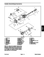
Figure 32
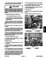
A. Remove extension spring from the neutral lever.
B. Loosen two (2) socket head screws (item 8, Fig.
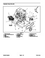
1.
2.
3.
4.
5.
6.
Hydraulic pump
7.
8.
9.
10. Lock nut
11. Pump shield
Trunnion clamp
Socket hd screw (2 used)
Washer head screw
Cap screw (2 used)
Control bracket
Flange nut (2 used)
Flat washer
32)
that secure pump lever to pump trunnion shaft.
Pump lever
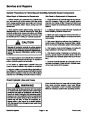
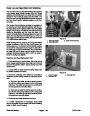
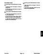
C. Remove two (2) cap screws with flange nuts
(items 2 and 4, Fig. 32) and washer head screw (item
9,
Fig. 32) that secures control bracket to hydraulic
pump.
1
3
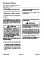
D. Carefully lift pump control assembly and position
away from pump.
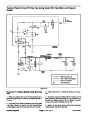
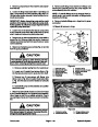
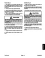
7.
Disconnect all hydraulic hoses and tubes connected
to the hydraulic fittings on the hydraulic pump assembly.
Allow hoses to drain into a suitable container. Plug or
cap openings of pump and hoses to prevent contamina-
tion.
4
3
2
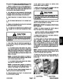
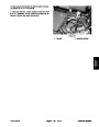
CAUTION
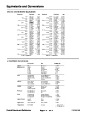
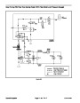
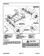
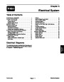
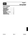
Figure 33
Support hydraulic pump when removing it from
the pump support to prevent the pump from fal-
ling and causing personal injury.
1.
2.
Extension spring
Socket head screw
3. Flange nut/cap screw
4. Washer head screw
ProCore 648
Page 4 – 39
Hydraulic System
| Categories | Lawn Mower Manual, Sprinkler and Irrigation Manuals, Toro Sprinkler and Irrigation Manuals |
|---|---|
| Tags | Toro 648 |
| Download File |
|
| Document Type | Service Manual |
| Language | English |
| Product Brand | Toro. Customer Service Representatives are available by phone:
Monday - Friday 7:30 a.m. to 9:00 p.m. (CDT) - Saturday 8:00 a.m. to 8:00 p.m. (CDT) - Sunday 10:00 a.m. to 8:00 p.m. (CDT)
Canada 1-888-225-4886 USA 1-888-384-9939, Lawn Mower |
| Document File Type | |
| Publisher | toro.com |
| Wikipedia's Page | Toro Company |
| Copyright | Attribution Non-commercial |
(0 votes, average: 0 out of 5)