


8.
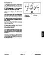
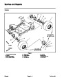
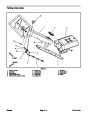
head frame (Figs. 22 and 23):
Disconnect upper end of lift cylinder from coring
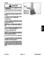
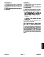
2. Position H–frame to machine frame making sure that
thrust washers are placed between H–frame and ma•
chine frame. Align both sides of H–frame to pivot shaft
holes in machine frame. Slide pivot shaft into H–frame
and machine frame.
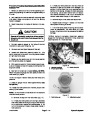
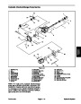
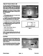
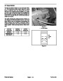
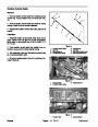
A. Remove retaining ring from one end of cylinder
pin that secures lift cylinder to coring head frame.
B. Pull cylinder pin from coring head frame and lift
cylinder. Locate and retrieve two (2) thrust washers
and two (2) spacers as pin is removed.
3.
of H–frame to pivot shaft holes in coring head frame.
Slide pivot shaft into H–frame and coring head frame.
Position coring head to allow alignment of both sides
C. Rotate lift cylinder toward front of machine.
4.
Complete assembly of coring head to machine in the
reverse order of disassembly.
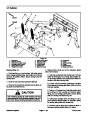
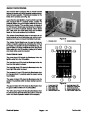
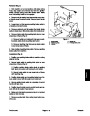
9.
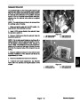
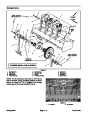
Disconnect wire harness connectors from limit
switches on depth actuator assembly.
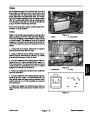
10.Remove
frame (Fig. 24). Position switch bracket with proximity
switches still attached away from H–frame.
proximity switch bracket from machine
2
11.
Remove right rear wheel from machine (see Wheel
Removal in Service and Repairs section of Chapter 6 –
Chassis). Make sure that machine is supported well with
jackstands or blocking.
1
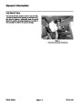
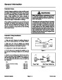
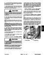
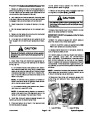
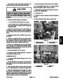
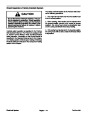
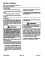
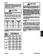
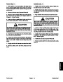
CAUTION
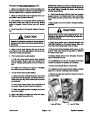
The coring head assembly weighs approximate•
ly 650 pounds (294.8 kg). Make sure that proper
lift or hoist is used to support coring head during
repairs.
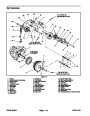
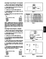
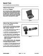
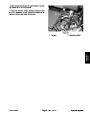
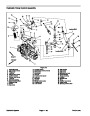
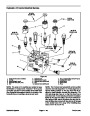
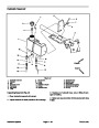
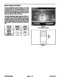
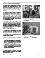
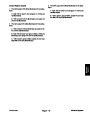
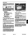
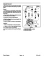
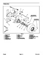
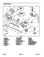
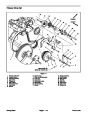
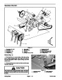
Figure 25
1.
Bearing housing
2.
Lifting eyelet
2
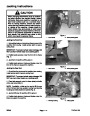
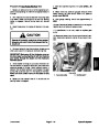
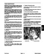
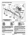
12.Using
suitable lift or hoist, support coring head using
lifting eyelets on coring crankshaft as lift points (Fig. 25).
Once coring head is well supported, remove service
latch from coring head.
1
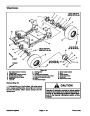
13.Remove
and coring head frame.
upper link assemblies from machine frame
2
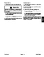
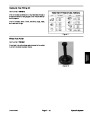
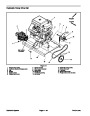
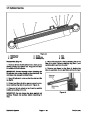
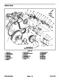
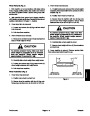
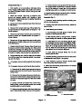
17.720”
to 17.780”
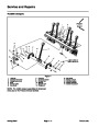
14.Remove
(item 13) that secure end of pivot shafts to machine.
flange nuts (item 15) and carriage screws
(45.0
to 45.2 cm)
15.Carefully
slide pivot shafts from H–frame. Locate
and retrieve thrust washers (item 12) from between H–
frame and machine frame.
16.Remove
H–frame from machine.
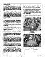
Assembly (Fig. 21)
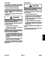
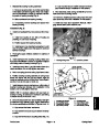
If upper links were disassembled, install rod ends
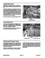
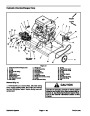
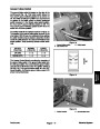
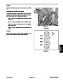
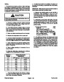
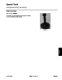
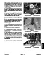
Figure 26
1.
Upper link
2.
Rod end
1.
equally to make link assembly 17.720” to 17.780” (45.0
to 45.2 cm) long (rod center to rod center) (Fig. 26).
IMPORTANT: When installing pivot shaft to H–
frame, make sure that both sides of H–frame are
aligned with holes in machine frame before instal•
ling pivot shaft.
Coring Head
Page 7 – 18
ProCore 648
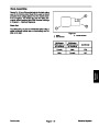
| Categories | Lawn Mower Manual, Sprinkler and Irrigation Manuals, Toro Sprinkler and Irrigation Manuals |
|---|---|
| Tags | Toro 648 |
| Download File |
|
| Document Type | Service Manual |
| Language | English |
| Product Brand | Toro. Customer Service Representatives are available by phone:
Monday - Friday 7:30 a.m. to 9:00 p.m. (CDT) - Saturday 8:00 a.m. to 8:00 p.m. (CDT) - Sunday 10:00 a.m. to 8:00 p.m. (CDT)
Canada 1-888-225-4886 USA 1-888-384-9939, Lawn Mower |
| Document File Type | |
| Publisher | toro.com |
| Wikipedia's Page | Toro Company |
| Copyright | Attribution Non-commercial |
(0 votes, average: 0 out of 5)