


7.
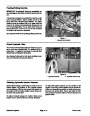
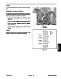
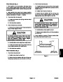
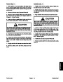
Disassemble bearing housing assembly:
D. Lock nuts that secure rotolink dampers to frame
(see Rotolink Damper Installation in this section).
A. Remove cap screw (item 1) and flat washer (item
2)
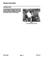
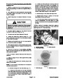
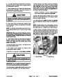
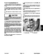
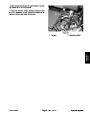
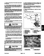
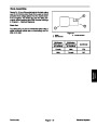
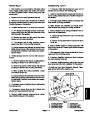
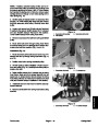
ment of identification number on crankarm with tim-
ing mark on bearing housing (Fig. 9).
that fasten crankarms together. Take note of align-
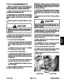
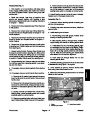
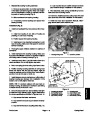
9. After assembly, rotate coring crankshaft by hand to
make sure that no binding occurs.
10.If
removed, install secondary coring head drive belt
B. Slide crankarms from bearing housing.
(see Secondary Drive Belt Installation in this section).
C. If necessary, remove bearings and spacer from
bearing housing.
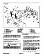
11.Install rear hood (see Operator’s Manual). Disen-
gage service latch before machine use.
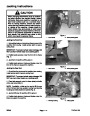
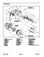
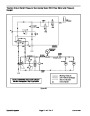
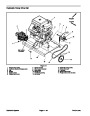
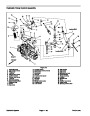
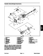
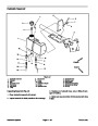
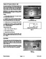
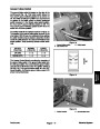
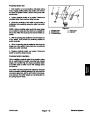
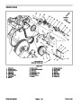
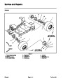
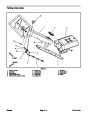
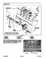
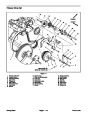
Installation (Fig. 8)
2
1.
Install new bearings if they were removed from hous-
ing:
A. Install new bearing in one side of housing by
pressing on outer race of bearing.
1
B. Position spacer into bearing housing.
2
C. Install second new bearing by pressing on outer
race of bearing. Make sure that spacer is centered
between bearings.
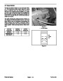
2.
Thoroughly apply antisieze lubricant to splines of
crankarms.
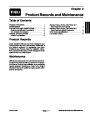
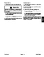
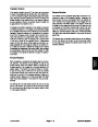
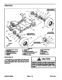
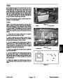
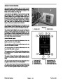
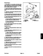
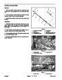
Figure 9
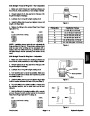
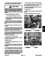
3.
that correct identification number on crankarm is aligned
with timing mark on bearing housing (Fig. 9).
Install crankarms into bearing housing. Make sure
1.
Housing timing mark
2. Crankarm position
1
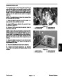
4.
retain crankarms. Do not fully tighten cap screw.
Install cap screw (item 1) and flat washer (item 2) to
150 to 170 ft–lb
(203 to 230 N–m)
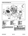
5.
6.
Drive new spring pins into coring head frame holes.
Position bearing housing assembly to coring head
2
3
4
frame and secure with four (4) cap screws, eight (8)
hardened washers and four (4) lock nuts. Torque fasten-
ers from 70 to 80 ft–lb (95 to 108 N–m).
8
7
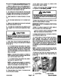
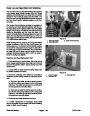
7.
Install stomper arms to crankarms on either side of
bearing housing (see Stomper Arm Installation in this
section). Do not fully tighten fasteners.
6
5
NOTE: With #1 crankarm aligned with cast mark on
bearing housing, all subsequent crankarm cast timing
numbers must be in line from 1 to 6.
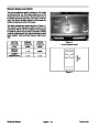
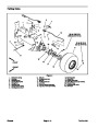
70
to 80 ft–lb
to 108 N–m)
(95
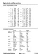
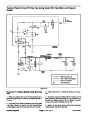
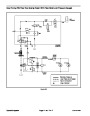
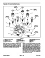
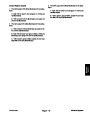
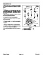
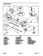
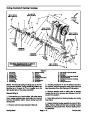
Figure 10
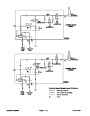
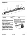
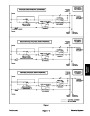
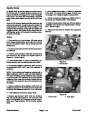
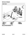
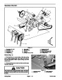
8.
en fasteners in the following order. Tighten fasteners to
the torque specifications identified in Figures 8 and 10:
Once all components have been installed, fully tight-
1.
2.
3.
4.
Coupling (#3 shown)
Iso mount (2 used)
Coupling (#2 shown)
Cap screw (2 used)
5.
6.
7.
8.
Coupling plate
Cap screw (4 used)
Lock nut (2 used)
Flat washer (2 used)
A. Cap screws that fasten crankarms.
B. Cap screws that secure top and bottom of stomp-
er arms.
C. Cap screws that secure coupling plates (Fig. 10).
ProCore 648
Page 7 – 9
Coring Head
| Categories | Lawn Mower Manual, Sprinkler and Irrigation Manuals, Toro Sprinkler and Irrigation Manuals |
|---|---|
| Tags | Toro 648 |
| Download File |
|
| Document Type | Service Manual |
| Language | English |
| Product Brand | Toro. Customer Service Representatives are available by phone:
Monday - Friday 7:30 a.m. to 9:00 p.m. (CDT) - Saturday 8:00 a.m. to 8:00 p.m. (CDT) - Sunday 10:00 a.m. to 8:00 p.m. (CDT)
Canada 1-888-225-4886 USA 1-888-384-9939, Lawn Mower |
| Document File Type | |
| Publisher | toro.com |
| Wikipedia's Page | Toro Company |
| Copyright | Attribution Non-commercial |
(0 votes, average: 0 out of 5)