


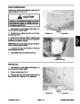
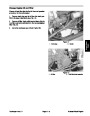
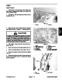


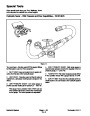


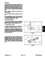
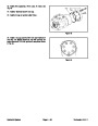
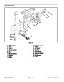
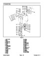
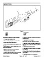
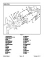
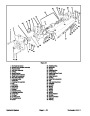

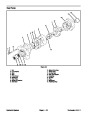


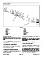

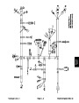
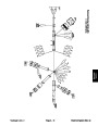
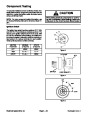
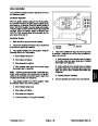


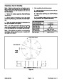
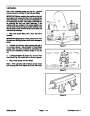


Disassemble Planetary Wheel Drive
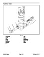
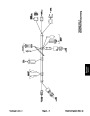
that can be assembled into the ring grooves of the
spindle shaft above the bearing cone. Bearing should
have from 0.000 to 0.006 inches (0.00 to 0.15mm) of
end play when the proper retaining ring is installed.
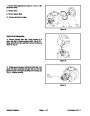
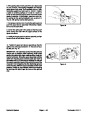
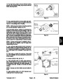
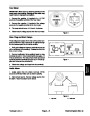
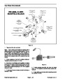
1.
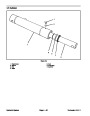
Slide coupling (1) from the splines on the input shaft
(2).
2.
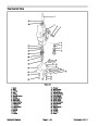
Remove disengage cover (18).
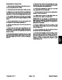
Position assembly upright on the face of spindle (3).
5.
pilot end of the input shaft (2). Assemble washer (26),
spring (27), second washer (26), second retaining ring
(25),
the input shaft. Some shafts have a shoulder and re-
quire only one retaining ring.
Assemble retaining ring (25) in the groove opposite
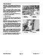
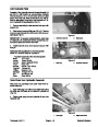
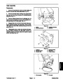
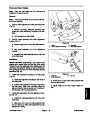
3.
Remove bolts (17) and large cover (19). The disen-
and third retaining ring (29) in the middle groove of
gage plunger (22) usually remains with the cover. Re-
move plunger and O−ring from the cover on the end of
the input shaft.
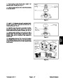
6.
the spindle.
Assemble splined end of the input shaft down into
4.
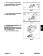
on the thrust face of the cover.
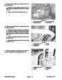
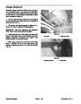
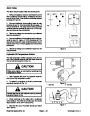
A thrust washer (23) will usually remain in position
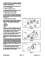
7.
splined end of spindle.
Assemble secondary carrier splines over the
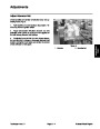
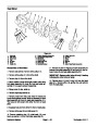
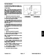
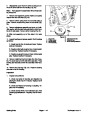
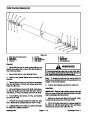
5.
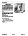
(12)
Remove primary sun gear (13) and thrust washer
from the end of the input shaft. Remove primary
carrier assembly (15).
8.
Apply a bead of RTV compound or equivalent to the
hub face that mates with ring gear (24). Assemble end
of the ring gear having 6 or 12 bolt holes against the hub
with the bolt holes of the hub and ring gear aligned. As-
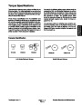
semble six 3/8−24x1−7/8 inch hex head bolts. Torque
bolts from 39 to 49 ft−lb (5.4 to 6.8 kg−m). If grade 8 bolts
are used, torque bolts from 52 to 60 ft−lb (7.2 to 8.3
kg−m). Grade 8 bolts can be identified by the 6 radial
lines on bolt head.
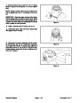
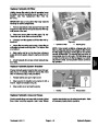
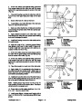
6.
necessary to remove the ring gear (24) first if difficulty
is encountered in removing the carrier.
Remove secondary carrier assembly (20). It may be
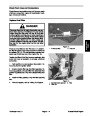
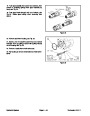
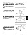
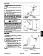
7.
move retaining rings, washers, and spring from the input
shaft only if replacement is required.
Remove input shaft (2) from the spindle (3). Re-
8.
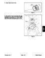
Remove ring gear (24). It may be necessary to strike ring
gear with a rubber mallet to loosen from hub.
Remove 6 or 12 bolts from the hub and ring gear.
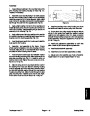
9.
Assemble primary carrier and sun gear into the ring
gear. It is necessary to rotate the carrier and pinion to
align the sun gear teeth with the secondary pinion and
primary pinions with ring gear teeth. Assemble primary
sun gear (13) over the input shaft. Rotate sun gear to
align the shaft to gear splines and gear teeth.
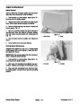
NOTE: Use snap ring expander tool to remove the re-
taining ring.
9.
Remove large retaining ring (28) from in front of
10.
shaft and against the shoulder of shaft.
Assemble small thrust washer (12) over the input
the tapered bearing. Lift hub (8) from the spindle. If
bearings are not a loose fit, it may be necessary to
press spindle from the hub.
11.
Assemble O−ring (21) in the groove of the disen-
gage plunger (22). Assemble plunger over the end of in-
put shaft and against the thrust washer.
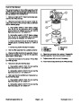
10.
from the hub. Inspect bearing cups (6) in position and re-
move only if replacement is required.
Remove oil seal (4) and bearing cones (5 and 9)
12.
Lubricate O−ring in the groove of the engage plung-
er. Assemble thrust washer (23) with tangs engaged
with the large cover (19). Apply a bead of RTV com-
pound or equivalent to the end face of the ring gear. As-
semble cover over the plunger as holes of cover and ring
gear are aligned. Assemble eight 5/16−18x1 inch hex
head bolts. Torque bolts from 20 to 25 ft−lb (2.8 to 3.5
kg−m).
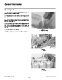
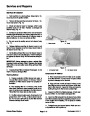
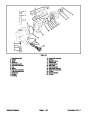
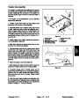
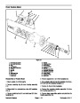
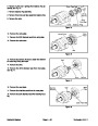
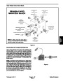
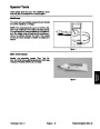
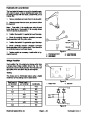
Assembly of the Planetary Wheel Drive
1.
Press a new bearing cup (6) into each side of the
hub (8).
2.
Assemble bearing cone (5) into the cup (6) at the
seal end of the hub. Press a new oil seal (4) into the hub.
3.
Position spindle (3) upright on bench. Lubricate lips
13. If the wheel is to be used to drive the vehicle, as-
semble disengage cover (18) with the dimpled center
protruding out. Assemble and torque two 5/16−18x3/4
inch bolts. Torque bolts from 10 to 20 (1.4 to 2.8 kg−m).
of oil seal (4) and lower hub onto the spindle. Hub (8)
should be centered as it is lowered over the spindle to
prevent seal damage.
4.
the bearing cup (6). Select thickest retaining ring (28)
Assemble bearing cone (9) over the spindle and into
14. Invert Power Wheel assembly. Assemble coupling
(1) with the counterbore out to the input shaft.
Axles and Brakes
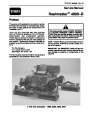
Reelmaster 4000−D
Page 6 − 8
| Categories | Lawn Mower Manual, Sprinkler and Irrigation Manuals, Toro Sprinkler and Irrigation Manuals |
|---|---|
| Tags | Toro 4000 D, Toro 98958SL |
| Download File |
|
| Document Type | Catalog |
| Language | English |
| Product Brand | Toro. Customer Service Representatives are available by phone:
Monday - Friday 7:30 a.m. to 9:00 p.m. (CDT) - Saturday 8:00 a.m. to 8:00 p.m. (CDT) - Sunday 10:00 a.m. to 8:00 p.m. (CDT)
Canada 1-888-225-4886 USA 1-888-384-9939, Lawn Mower |
| Document File Type | |
| Publisher | toro.com |
| Wikipedia's Page | Toro Company |
| Copyright | Attribution Non-commercial |
(0 votes, average: 0 out of 5)