


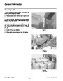
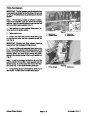


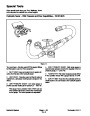


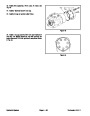
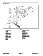
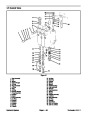
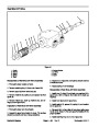
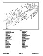


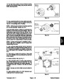

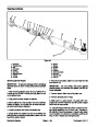


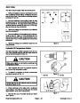
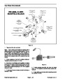


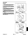
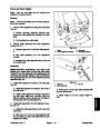


Inspection of Reel Motor
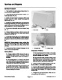
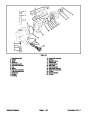
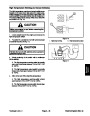
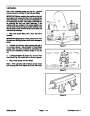
Reassembly of Reel Motor
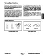
GENERAL
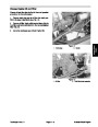
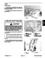
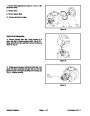
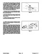
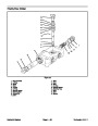
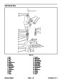
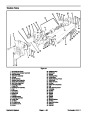
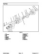
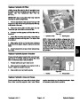
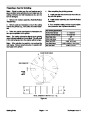
1. If the relief valve kit was removed, install ball (20),
spring (19), shim (18), new O−ring (16), and plug (17)
into the back plate (21). Torque plug from 10 to 12 ft−lb
1.
2.
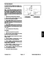
Clean and dry all parts.
(1.4
to 1.7 kg−m).
Remove nicks and burrs from all parts with emery
cloth.
2.
(14),
Retaining ring (12), shaft seal (13), back−up washer
and O−rings (5) should be replaced as new parts.
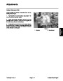
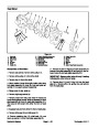
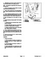
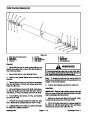
GEAR ASSEMBLY
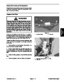
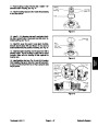
3.
body (6).
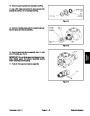
Install O−rings (5) in grooves of front plate (8) and
1.
keyway.
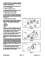
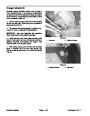
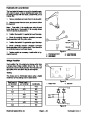
Inspect drive gear assembly (3) for broken or cracked
4.
tion of scribe line.
Install body (6) in front plate assembly (8) noting posi-
2.
shafts at bearing point for rough surfaces and excessive
wear.
Inspect both the drive gear (3) and idler gear (2)
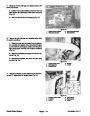
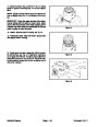
5.
Install dowel pins (7) in body (6) and front plate as-
sembly (8).
3.
If shaft measures less than .686 in bearing area, the
gear assembly should be replaced. (One gear assembly
may be replaced separately. Shafts and gears are avail-
able as assemblies only.)
6.
and front plate bushing.
Dip gear assemblies (2 & 3) into oil and slip into body
7.
scribe line. Install cap screws (9), draw up bolts evenly
and torque to 22−25 ft. lbs.
Install back plate assembly (21) noting position of
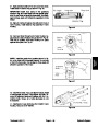
4.
replaced.
If gear width is below 1.327, gear assembly should be
5.
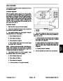
Inspect gear face for scoring and excessive wear.
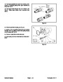
8.
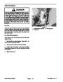
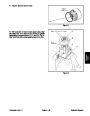
Install new back−up washer (14) on drive shaft.
6.
groove.
Retaining ring (12) on shaft assemblies should be in
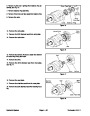
Oil shaft seal (13) liberally. Work shaft seal (13) over
drive shaft taking care not to cut rubber sealing lip.
7.
emery cloth.
If edge of gear teeth are sharp, break edge with
9.
Install new retaining ring (12).
Seat shaft seal (13) by tapping with plastic hammer.
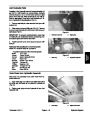
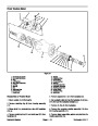
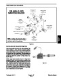
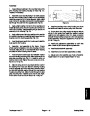
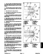
FRONT PLATE, BODY, BACK PLATE, AND RELIEF
VALVE
10.
11.
Replace key (4) in drive shaft (3).
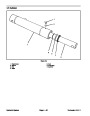
Install drive pulley (11) on drive shaft.
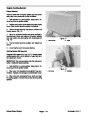
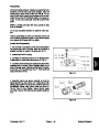
1.
Inspect I.D. of bushings in front plate (8), body (6),
and back plate (21). If I.D. exceeds .693, front plate,
body, or back plate should be replaced. (Bushings are
not available as separate items.)
12. Tighten set screws (10) in drive pulley (11).
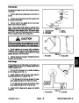
2.
Back plate assembly (21) should be replaced if I.D. of
gear pocket exceeds 1.719.
3.
Check for scoring on face of front plate (8), body (6),
and back plate (21). If wear exceeds .0015, front plate,
body, or back plate should be replaced.
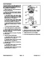
4.
If the relief valve kit (15) was removed, inspect valve
bore in the back plate (21) for dirt, debris, and damage.
Clean bore of dirt and debris. Replace back plate if bore
or valve seating surfaces are damaged.
IMPORTANT: The plug (17), shim (18), spring (19),
and ball (20) must be replaced as a complete unit.
5.
If the relief valve kit was removed, inspect plug (17),
shim (18), spring (19), and ball (20) for wear and dam-
age. Replace parts as necessary.
Reelmaster 4000−D
Page 4 − 53
Hydraulic System
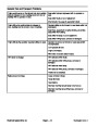
| Categories | Lawn Mower Manual, Sprinkler and Irrigation Manuals, Toro Sprinkler and Irrigation Manuals |
|---|---|
| Tags | Toro 4000 D, Toro 98958SL |
| Download File |
|
| Document Type | Catalog |
| Language | English |
| Product Brand | Toro. Customer Service Representatives are available by phone:
Monday - Friday 7:30 a.m. to 9:00 p.m. (CDT) - Saturday 8:00 a.m. to 8:00 p.m. (CDT) - Sunday 10:00 a.m. to 8:00 p.m. (CDT)
Canada 1-888-225-4886 USA 1-888-384-9939, Lawn Mower |
| Document File Type | |
| Publisher | toro.com |
| Wikipedia's Page | Toro Company |
| Copyright | Attribution Non-commercial |
(0 votes, average: 0 out of 5)