


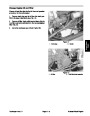
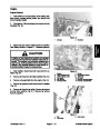


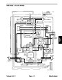


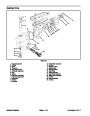
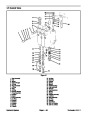
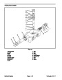
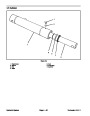
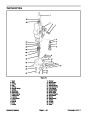
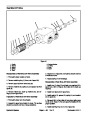
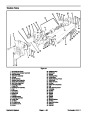
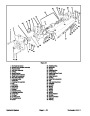

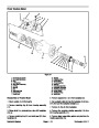


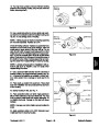

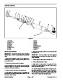


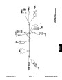
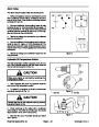
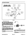


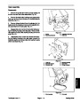
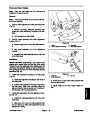


Disassembly of Lift Control Valve
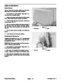
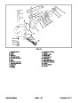
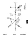
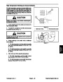
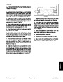
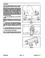
Assembly of Lift Control Valve
1.
2.
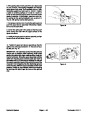
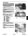
Plug all ports and clean outside of valve thoroughly.
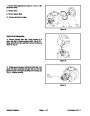
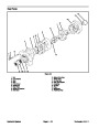
Remove cap assemblies (28). Do not remove retain-
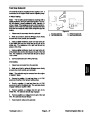
1. Thoroughly clean and dry all parts. Apply a light coat-
ing of clean hydraulic oil to parts prior to assembly.
ing rings (26) from spools unless spring (25) is broken.
NOTE: All O−rings, back−up washers, wiper seals and
nylon poppets should be replaced as new items.
3.
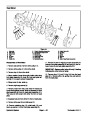
Remove spools (13) from body (8).
2.
bores.
Install new O−rings (22) in proper grooves in spool
NOTE: Spools and spool bores are matched sets. Be
sure each spool is identified with the correct body spool
bore.
3. Install relief valve components (20, 19, 18, 17, 16)
with new O−ring (15) on plug (14).
4.
5.
6.
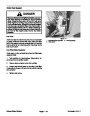
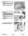
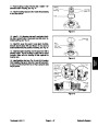
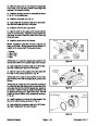
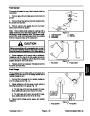
Remove bushings (23) and O−rings (22) from spools.
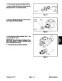
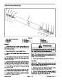
Remove plugs (11).
4.
O−rings (9).
Install plugs (11) with new back−up washers (10) and
Remove plugs (30), springs (31), poppets (33), seats
and plungers (37, 29).
5.
Install plungers (37, 29).
(35)
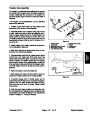
IMPORTANT: Check location and positioning of
plungers during installation.
IMPORTANT: Check location and positioning of
plungers when removing from body to assure prop-
er assembly.
6. Install new O−rings (36) on seats (35). Install new
back−up washers (10) and O−rings (9) on plugs (30).
7.
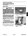
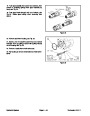
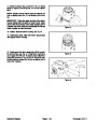
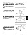
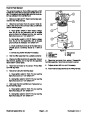
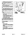
Remove plugs (6).
7.
Install seats (35), new poppets (33), and plugs (30).
8.
Remove plugs (1), discs (2), springs (3) and detent
plungers (4).
8. Install plugs (6) with new O−rings (7).
9.
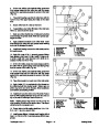
ers (16, 17, 18), spring (19) and poppet (20).
Remove locknut (34), washer (12), plug (14), wash-
9. Install detent plungers (4), springs (3), discs (2), and
plugs (1) with new O−rings (5).
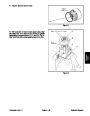
10.
plugs and seats.
Remove all O−rings and back−up rings from all
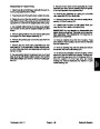
10. If retaining ring (27) has been removed to replace
spool spring (25), install washer (24), spring (25),
spacer (26), and secure with retaining ring (27).
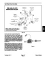
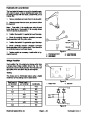
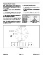
Inspection of Lift Control Valve
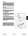
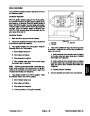
11.
(22)
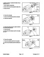
spools in clean hydraulic oil and install spool assemblies
in proper location.
Slide bushings (23) over spools. Slide new O−rings
over spools and position next to bushings. Dip
1.
excessive wear.
Remove all nicks and burns from parts and inspect for
2.
Inspect all plungers and poppet seats for burrs or
roughness.
12.
20
Install spool caps (28) and tighten to a torque of
− 25 ft−lb.
3.
Inspect spool springs (25), relief valve spring (19),
lockout springs (31), and detent springs (3) for break-
age.
13.
Install new wiper seals (38).
4.
If spools (13) have excessive wear, the valve be-
comes non−serviceable as the spools and spool bores
are matched and damaged spools cannot be replaced.
5.
Inspect relief valve poppet (20) for breakage or wear.
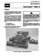
Reelmaster 4000−D
Page 4 − 59
Hydraulic System
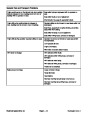
| Categories | Lawn Mower Manual, Sprinkler and Irrigation Manuals, Toro Sprinkler and Irrigation Manuals |
|---|---|
| Tags | Toro 4000 D, Toro 98958SL |
| Download File |
|
| Document Type | Catalog |
| Language | English |
| Product Brand | Toro. Customer Service Representatives are available by phone:
Monday - Friday 7:30 a.m. to 9:00 p.m. (CDT) - Saturday 8:00 a.m. to 8:00 p.m. (CDT) - Sunday 10:00 a.m. to 8:00 p.m. (CDT)
Canada 1-888-225-4886 USA 1-888-384-9939, Lawn Mower |
| Document File Type | |
| Publisher | toro.com |
| Wikipedia's Page | Toro Company |
| Copyright | Attribution Non-commercial |
(0 votes, average: 0 out of 5)