


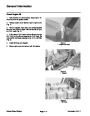
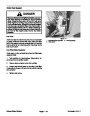


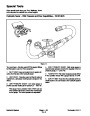


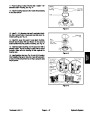
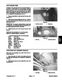
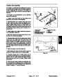


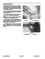

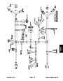
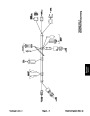
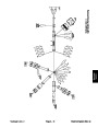
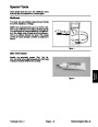
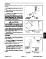


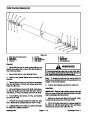


Traction Rod Assembly
The traction rod assembly allows adjustment to prevent
the machine from creeping when the traction pedal is in
neutral. Additionally, the rod block on the traction rod
prevents traction pedal movement unless the brake is
released.
2
1
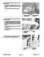
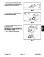
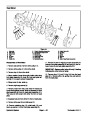
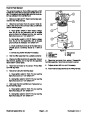
If the traction rod is disassembled, use the following
steps during assembly.
3
4
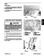
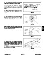
1.
Position neutral lock bracket so that socket head
5
screws are in the center of mounting slots.
9
8
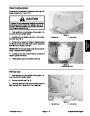
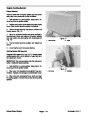
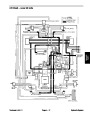
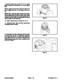
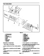
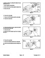
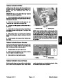
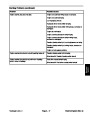
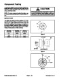
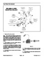
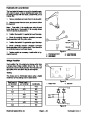
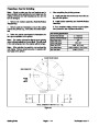
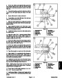
2.
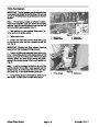
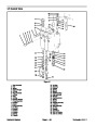
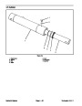
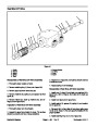
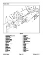
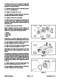
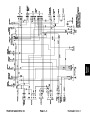
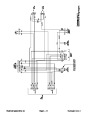
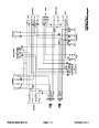
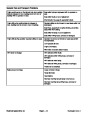
Assemble traction rod to machine using Figure 62 as
a guide. Make sure that rod block is positioned down-
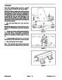
ward to engage traction lock lever. Overall traction rod
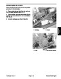
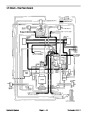
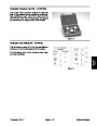
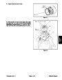
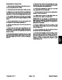
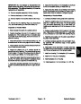
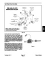
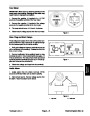
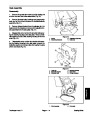
length (center to center) should be 26.060” (66.2 cm).
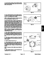
The distance between pump lever clevis center and rod
block should be from 8.250” to 8.310” (20.96 to 21.11
cm) (Fig. 63).
6
7
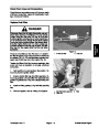
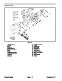
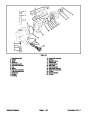
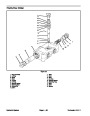
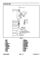
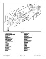
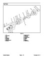
Figure 62
1.
2. Pump lever
Traction pedal
6. Neutral lock bracket
7. Switch
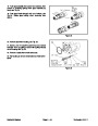
3.
Do not fully tighten fasteners.
Attach traction rod to traction pedal and pump lever.
3.
4.
5.
Socket hd screw (2 used)
Flat washer (2 used)
Lock washer (2 used)
8. Traction rod
9. Rod block
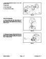
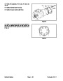
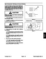
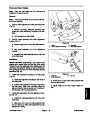
4.
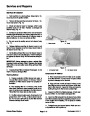
Make sure that ground speed control lever on ma-
chine is in the fully forward position.
5.
Depress traction pedal fully to engage ground speed
control lever and make sure that pump lever has
reached the full rearward stoke. If pump lever does not
reach full stroke or if traction pedal does not engage
ground speed control lever, adjust traction control rod
ends as needed. Make sure that rod block stays in align-
ment with traction lock lever during any control rod ad-
justment.
26.060”
(66.2
cm)
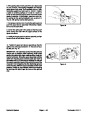
6.
Tighten all traction control rod fasteners.
8.250
(20.96 to 21.11 cm)
to 8.310”
7.
Start engine and make sure that machine does not
creep when traction pedal is in the neutral position.
Figure 63
8.
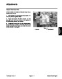
If machine creeps when in neutral, loosen two (2)
socket head screws that secure neutral lock bracket to
machine (Fig. 62). Slide neutral lock bracket until ma-
chine does not move when in neutral. Tighten socket
head screws.
9.
Verify that hand brake functions correctly after trac-
tion rod assembly and adjustments are completed (see
Hand Brake and Traction Switches in the Adjustments
section of Chapter 6 − Axles and Brakes).
Reelmaster 4000−D
Page 4 − 67 Rev. B
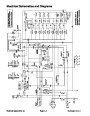
Hydraulic System
| Categories | Lawn Mower Manual, Sprinkler and Irrigation Manuals, Toro Sprinkler and Irrigation Manuals |
|---|---|
| Tags | Toro 4000 D, Toro 98958SL |
| Download File |
|
| Document Type | Catalog |
| Language | English |
| Product Brand | Toro. Customer Service Representatives are available by phone:
Monday - Friday 7:30 a.m. to 9:00 p.m. (CDT) - Saturday 8:00 a.m. to 8:00 p.m. (CDT) - Sunday 10:00 a.m. to 8:00 p.m. (CDT)
Canada 1-888-225-4886 USA 1-888-384-9939, Lawn Mower |
| Document File Type | |
| Publisher | toro.com |
| Wikipedia's Page | Toro Company |
| Copyright | Attribution Non-commercial |
(0 votes, average: 0 out of 5)