

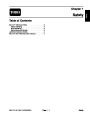


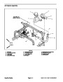
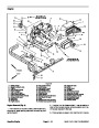
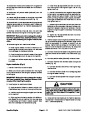


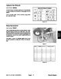
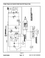
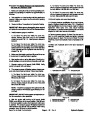
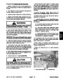


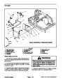
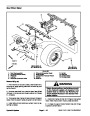

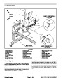


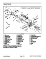

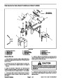


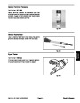
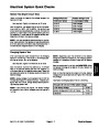
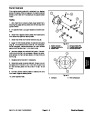
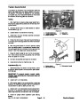


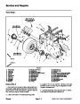

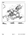
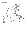
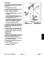
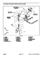
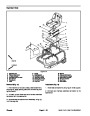


Charge, Start and Interlock Relays
Three (3) relays are used on the machine: start relay,
charge relay and interlock relay. The relays are attached
to a bracket under the seat (Fig. 13). The relays are iden-
tical and are identified by a tag on the wire harness relay
connector.
1
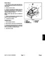
The start relay is used in the starting circuit. When ener-
gized, the start relay provides current to energize the
starter solenoid.
2
When the charge relay is energized, a circuit from the al-
ternator to the battery is completed to allow battery
charging.
The interlock relay is used in conjunction with the seat
switch, the neutral switch and diodes D1 and D2 to form
the interlock system on the machine. When the interlock
relay is energized, the engine magneto system will func-
tion. During operation, if the interlock relay should be
de–energized (e.g. operator rises out of the seat with the
traction pedal depressed), the magneto will be
grounded and the engine will stop.
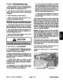
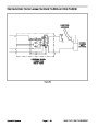
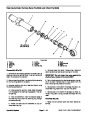
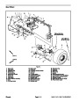
Figure 13
2.
1.
Bracket
Relay
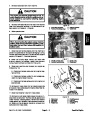
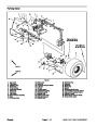
86
87A
87
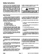
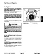
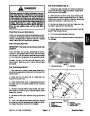
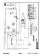
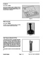
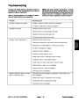
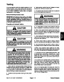
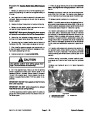
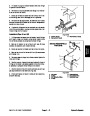
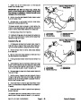
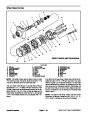
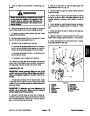
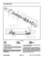
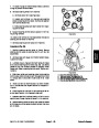
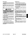
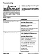
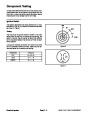
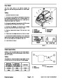
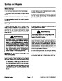
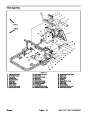
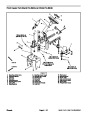
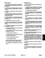
Testing
NOTE: Prior to taking small resistance readings with a
digital multimeter, short the meter test leads together.
The meter will display a small resistance value (usually
85
30
0.5
ohms or less). This resistance is due to the internal
resistance of the meter and test leads. Subtract this val-
ue from the measured value of the component you are
testing.
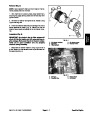
Figure 14
7.
Connect multimeter (ohms setting) leads to relay ter-
1.
stop engine, apply parking brake and remove key from
ignition switch.
Park machine on a level surface, lower attachment,
minals 30 and 87A. Apply +12 VDC to terminal 85. The
relay should make and break continuity between termi-
nals 30 and 87A as +12 VDC is applied and removed
from terminal 85.
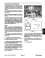
2.
Tilt operator seat up to gain access to relays.
8.
relay terminals. Connect machine wire harness connec-
tor to relay.
Disconnect voltage and multimeter leads from the
3.
wire harness connector from the relay.
Locate relay to be tested. Disconnect the machine
4.
sistance between terminals 85 and 86 (Fig. 14). Resist-
ance should be between 70 and 90 ohms.
Using a multimeter (ohms setting), measure coil re-
9.
Lower operator seat.
5.
Connect multimeter (ohms setting) leads to relay ter-
minals 30 and 87. Ground terminal 86 and apply +12
VDC to terminal 85. The relay should make and break
continuity between terminals 30 and 87 as +12 VDC is
applied and removed from terminal 85.
6.
Disconnect voltage from terminal 85 and multimeter
lead from terminal 87.
Sand Pro & Infield Pro 3040/5040
Page 5 – 11
Electrical System
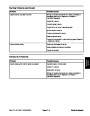
| Categories | Lawn Mower Manual, Sprinkler and Irrigation Manuals, Toro Sprinkler and Irrigation Manuals |
|---|---|
| Tags | Toro 3040, Toro 5040 |
| Download File |
|
| Document Type | Service Manual |
| Language | English |
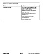
| Product Brand | Toro. Customer Service Representatives are available by phone:
Monday - Friday 7:30 a.m. to 9:00 p.m. (CDT) - Saturday 8:00 a.m. to 8:00 p.m. (CDT) - Sunday 10:00 a.m. to 8:00 p.m. (CDT)
Canada 1-888-225-4886 USA 1-888-384-9939, Lawn Mower |
| Document File Type | |
| Publisher | toro.com |
| Wikipedia's Page | Toro Company |
| Copyright | Attribution Non-commercial |
(0 votes, average: 0 out of 5)