

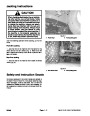


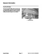
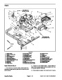


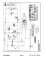


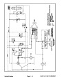


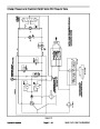
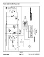
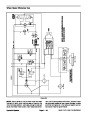
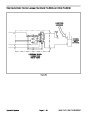


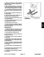
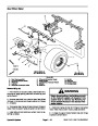

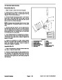


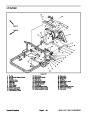
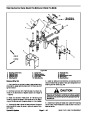

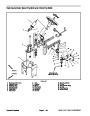
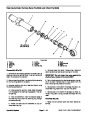

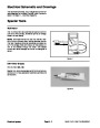
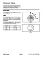
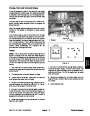


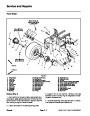

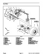
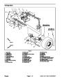
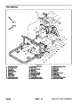
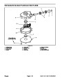
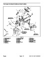


Steering Circuit (Sand Pro 5040 and Infield Pro 5040)
The charge pump in the hydrostat on Sand Pro 5040 and
Infield Pro 5040 machines supplies flow for the steering
circuit and for the implement lift circuit. Pump output
flows to the steering control valve before reaching the lift
control valve so the steering circuit has priority. Steering
circuit pressure is limited to 1100 PSI (75.9 bar) by the
implement relief valve (R1) located in the hydrostat.
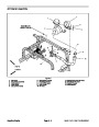
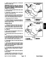
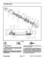
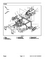
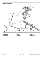
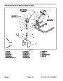
P port passes through the rotary meter and is directed
out port R. Pressure extends the steering cylinder for a
right turn. The rotary meter ensures that the oil flow to
the cylinder is proportional to the amount of the turning
on the steering wheel. Fluid leaving the cylinder flows
back through the spool valve, then out the T port of the
steering control valve and to the hydraulic tank.
When the steering wheel is not being turned and the en-
gine is running (hydrostat input shaft being rotated),
charge pump flow enters the steering control valve at
the P port and by–passes the rotary meter and steering
cylinder. Flow leaves the steering control valve through
the E port and is directed to the lift control valve.
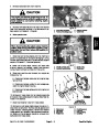
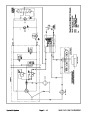
Left Turn
When a left turn is made with the engine running, the
turning of the steering wheel positions the steering con-
trol spool valve so that flow goes through the top of the
spool. Flow entering the steering control valve at the P
port passes through the rotary meter and is directed out
the L port. Pressure retracts the steering cylinder for a
left turn. The rotary meter ensures that the oil flow to the
cylinder is proportional to the amount of the turning on
the steering wheel. Fluid leaving the steering cylinder
flows back through the spool valve, then out the T port
of the steering control valve and returns to the hydraulic
tank.
Right Turn
When a right turn is made with the engine running, the
turning of the steering wheel positions the steering con-
trol spool valve so that flow goes through the bottom of
the spool. Flow entering the steering control valve at the
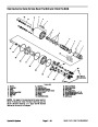
NOT TURNING
RIGHT TURN
LEFT TURN
(EXTENDING)
(RETRACTING)
Figure 7
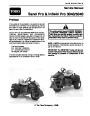
Sand Pro & Infield Pro 3040/5040
Page 4 – 15
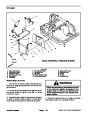
Hydraulic System
| Categories | Lawn Mower Manual, Sprinkler and Irrigation Manuals, Toro Sprinkler and Irrigation Manuals |
|---|---|
| Tags | Toro 3040, Toro 5040 |
| Download File |
|
| Document Type | Service Manual |
| Language | English |
| Product Brand | Toro. Customer Service Representatives are available by phone:
Monday - Friday 7:30 a.m. to 9:00 p.m. (CDT) - Saturday 8:00 a.m. to 8:00 p.m. (CDT) - Sunday 10:00 a.m. to 8:00 p.m. (CDT)
Canada 1-888-225-4886 USA 1-888-384-9939, Lawn Mower |
| Document File Type | |
| Publisher | toro.com |
| Wikipedia's Page | Toro Company |
| Copyright | Attribution Non-commercial |
(0 votes, average: 0 out of 5)