


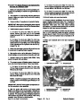


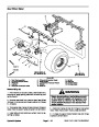


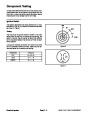


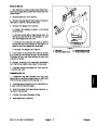


5.
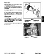
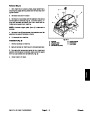
curing the hydraulic motor to the fork.
Remove both socket head screws and lock nuts se-
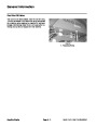
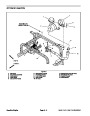
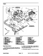
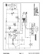
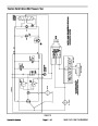
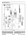
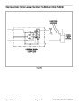
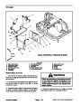
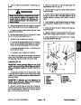
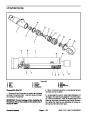
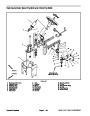
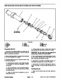
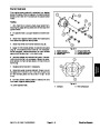
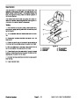
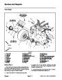
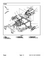
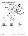
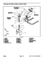
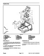
Installation (Fig. 2)
If wheel motor or hub was removed, install hub and
1.
IMPORTANT: Support wheel and wheel motor when
jacking up the front of the machine to prevent hy-
draulic tube damage.
motor (see Front Wheel Motor Installation in the Service
and Repairs section of Chapter 4 – Hydraulic System).
2.
3.
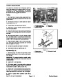
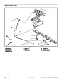
spindle and drive studs through wheel. Make sure valve
stem and hydraulic motor are on opposite sides of the
wheel.
Position hydraulic motor and hub to the front fork.
Install spindle to drive studs and wheel hub. Insert
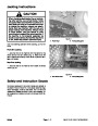
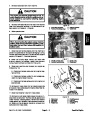
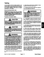
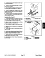
WARNING
Before jacking up the machine, review and follow
Jacking Instructions in Chapter 1 – Safety.
4.
For Sand Pro 5040 and Infield Pro 5040 machines,
secure front wheel as follows:
6.
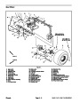
Jack up front of machine slowly until the hydraulic
motor and flangettes can be removed from the fork. Re-
move flangettes, spindle, wheel and motor from the fork.
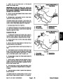
A. Install four (4) lug nuts onto drive studs.
B. Torque lug nuts evenly in a crossing pattern from
7.
Slide flangettes and bearing assembly from the
spindle. Separate flangettes from the bearing.
45
to 55 ft–lb (61 to 75 N–m).
5.
secure front wheel as follows:
For Sand Pro 3040 and Infield Pro 3040 machines,
8.
remove front wheel as follows:
For Sand Pro 5040 and Infield Pro 5040 machines,
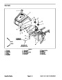
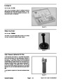
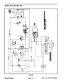
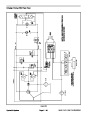
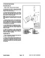
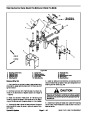
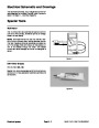
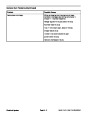
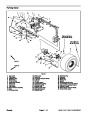
A. If studs were removed from wheel weight adapt-
ers, thread studs fully into the correct end of the
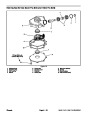
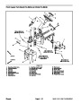
adapter (Fig. 3).
A. Remove four (4) lug nuts from the drive studs.
B. Remove wheel from the drive studs and spindle.
B. Install two (2) lug nuts and two (2) wheel weight
adapters with studs onto drive studs.
9.
remove front wheel as follows:
For Sand Pro 3040 and Infield Pro 3040 machines,
C. Torque lug nuts and wheel weight adapters even-
ly in a crossing pattern from 45 to 55 ft–lb (61 to 75
N–m).
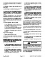
CAUTION
To prevent personal injury, make sure that
wheel weight is supported as it is removed
from the machine. Wheel weight weighs
approximately 25 pounds (11.4 kg).
CAUTION
To prevent personal injury, make sure that
wheel weight is supported as it is installed to
the machine. Wheel weight weighs approxi-
mately 25 pounds (11.4 kg).
A. Remove two (2) lock nuts and thrust washers that
secure wheel weight to wheel.
B. Carefully slide wheel weight from weight studs.
D. Carefully slide wheel weight onto weight studs.
C. Loosen and remove two (2) lug nuts and two (2)
wheel weight adapters with studs.
E. Secure wheel weight to wheel with two (2) thrust
washers and lock nuts.
D. Pull wheel from machine.
6
0o
30o + 5o
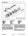
10.Separate
spindle from drive studs and wheel hub.
11.
Secure hydraulic motor and hub to the machine to
prevent damaging the hydraulic lines.
12.If
wheel motor or hub removal is necessary, see
Front Wheel Motor Removal in the Service and Repairs
section of Chapter 4 – Hydraulic System.
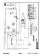
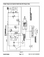
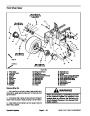
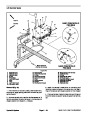
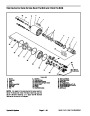
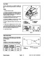
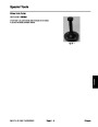
WHEEL STUD
WEIGHT STUD
(.500–13 UNC–2B)
(.500–20
UNF–2B)
Figure 3
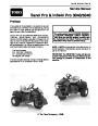
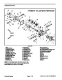
Sand Pro & Infield Pro 3040/5040
Page 6 – 5
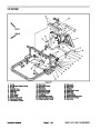
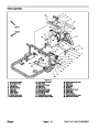
Chassis
| Categories | Lawn Mower Manual, Sprinkler and Irrigation Manuals, Toro Sprinkler and Irrigation Manuals |
|---|---|
| Tags | Toro 3040, Toro 5040 |
| Download File |
|
| Document Type | Service Manual |
| Language | English |
| Product Brand | Toro. Customer Service Representatives are available by phone:
Monday - Friday 7:30 a.m. to 9:00 p.m. (CDT) - Saturday 8:00 a.m. to 8:00 p.m. (CDT) - Sunday 10:00 a.m. to 8:00 p.m. (CDT)
Canada 1-888-225-4886 USA 1-888-384-9939, Lawn Mower |
| Document File Type | |
| Publisher | toro.com |
| Wikipedia's Page | Toro Company |
| Copyright | Attribution Non-commercial |
(0 votes, average: 0 out of 5)