


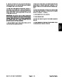


5.
poses.
Label all hydraulic connections for assembly pur-
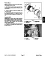
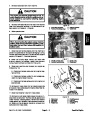
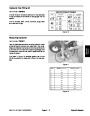
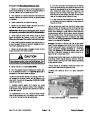
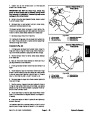
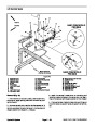
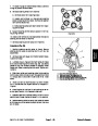
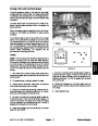
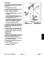
3. Secure lift lever pivot to lift control valve spool with
cap screw and lock nut (Fig. 41).
4.
lines and fittings.
Remove caps or plugs from disconnected hydraulic
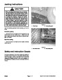
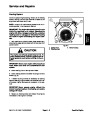
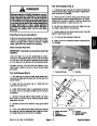
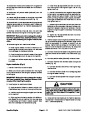
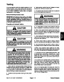
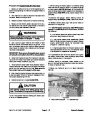
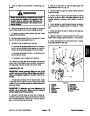
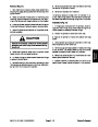
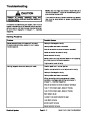
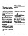
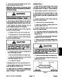
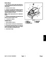
WARNING
5.
Position new o–rings and connect hydraulic lines to
Before disconnecting or performing any work
on the hydraulic system, all pressure in the
system must be relieved. See Relieving Hy-
draulic System Pressure in the General Infor-
mation section.
fittings on lift control valve. Use labels placed during the
removal process to properly install hoses to lift control
valve.
6.
in the Service and Repairs section of Chapter 6 – Chas-
sis).
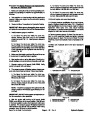
Install console to machine (see Console Installation
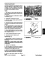
6.
valve. Allow hoses to drain into a suitable container.
Disconnect hydraulic lines from fittings on lift control
7.
Check and adjust oil level in hydraulic tank (see Op-
erator’s Manual).
7.
Put caps or plugs on disconnected lines and fittings
to prevent contamination.
8.
Operate machine functions slowly until air is out of
system (see Charge Hydraulic System in this section).
8.
Remove cap screw and lock nut that secure lift lever
pivot to lift control valve spool (Fig. 41).
9.
Check float position of lift lever and adjust if neces-
sary (see Operator’s Manual).
9.
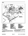
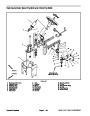
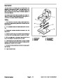
Remove lift control valve from machine:
A. Remove two (2) cap screws and lock nuts that se-
cure lift control valve and pivot bracket to machine.
Position lever assembly away from control valve.
13
5
7
4
6
B. Remove cap screw and lock nut that secures lift
control valve to frame.
3
2
9
8
1
C. Remove lift control valve from machine.
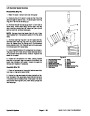
10.If
hydraulic fittings are to be removed from control
valve, mark fitting location and orientation to allow cor-
rect assembly. Remove fittings from control valve.
9
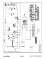
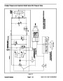
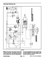
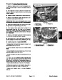
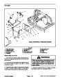
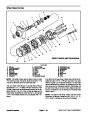
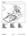
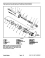
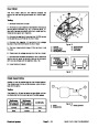
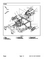
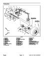
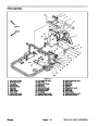
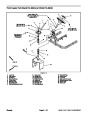
Installation (Fig. 40)
10
IMPORTANT: Upper hydraulic fitting on rear of lift
control valve is an orificed fitting. Make sure that fit-
tings are properly installed in control valve if re-
moved.
11
12
1.
If fittings were removed from lift control valve, install
fittings with new o–rings to lift control valve using marks
made during the removal process to properly locate and
orientate fittings.
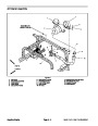
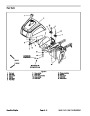
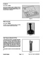
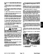
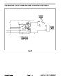
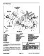
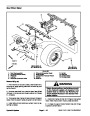
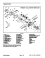
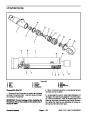
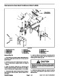
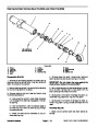
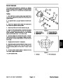
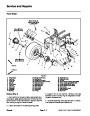
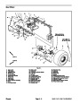
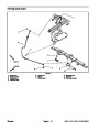
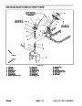
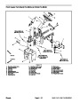
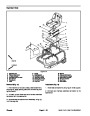
Figure 41
1.
2.
3.
4.
5.
6.
7.
Lift lever
Lock nut
Pivot
Curved washer
Roll pin
Clevis pin
Cotter pin
8.
9.
10. Pivot bracket
11. Cap screw
12. Lift control valve
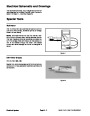
13. Knob
Offset link
Cap screw
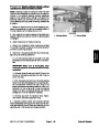
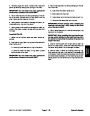
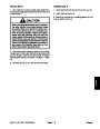
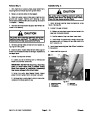
IMPORTANT: If fasteners are over–tightened, lift
control valve may bind. Make sure to properly
torque fasteners during assembly.
2.
sembly to control valve. Secure control valve to machine
with removed fasteners. Torque lock nuts (item 6) from
Position lift control valve to frame and lift lever as-
90
to 110 in–lbs (10.2 to 12.4 N–m).
Sand Pro & Infield Pro 3040/5040
Page 4 – 49
Hydraulic System
| Categories | Lawn Mower Manual, Sprinkler and Irrigation Manuals, Toro Sprinkler and Irrigation Manuals |
|---|---|
| Tags | Toro 3040, Toro 5040 |
| Download File |
|
| Document Type | Service Manual |
| Language | English |
| Product Brand | Toro. Customer Service Representatives are available by phone:
Monday - Friday 7:30 a.m. to 9:00 p.m. (CDT) - Saturday 8:00 a.m. to 8:00 p.m. (CDT) - Sunday 10:00 a.m. to 8:00 p.m. (CDT)
Canada 1-888-225-4886 USA 1-888-384-9939, Lawn Mower |
| Document File Type | |
| Publisher | toro.com |
| Wikipedia's Page | Toro Company |
| Copyright | Attribution Non-commercial |
(0 votes, average: 0 out of 5)