


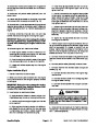


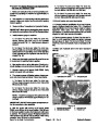
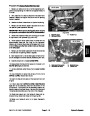


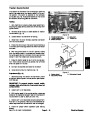


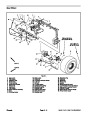
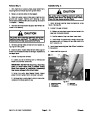
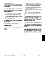


Lift Circuit
In addition to replenishing the closed loop traction circuit
with hydraulic oil from the tank, charge pump (P2) sup-
plies flow for the implement lift circuit and the steering
circuit on Sand Pro 5040 and Infield Pro 5040 machines.
Lift and steering circuit pressure is limited to 1100 PSI
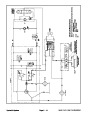
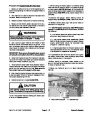
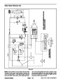
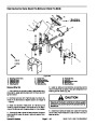
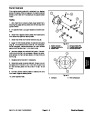
Moving the lift lever to the raise position allows the lift
control valve to direct fluid flow from the charge pump to
the rod side of the lift cylinder. The piston moves into the
cylinder pushing fluid out the piston end of the cylinder
and to the tank. As the cylinder rod retracts, the attach-
ment is raised. When the lift lever is released, the lift
valve returns to the neutral position and the attachment
is held in position.
(75.9
bar) by the implement relief valve (R1) located in
the hydrostat. On Sand Pro 5040 and Infield Pro 5040
machines, pump (P2) output flows to the steering con-
trol valve before reaching the lift valve so the steering
circuit has priority.
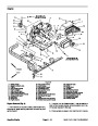
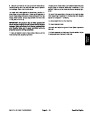
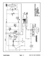
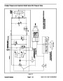
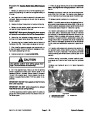
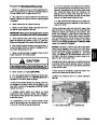
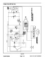
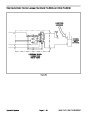
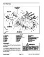
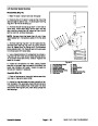
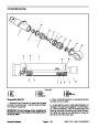
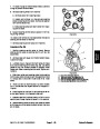
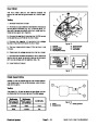
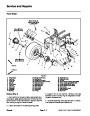
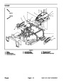
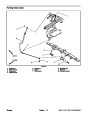
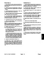
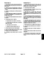
Moving the lift lever to the lower position allows the lift
control valve to direct fluid flow from the charge pump to
the piston side of the lift cylinder (Fig. 6). The piston
moves out of the cylinder pushing fluid out the rod end
of the cylinder and to the tank. As the cylinder rod ex-
tends, the attachment is lowered. When the lift lever is
released, the lift valve returns to the neutral position and
the attachment is held in position.
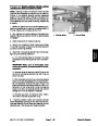
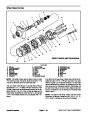
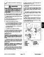
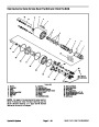
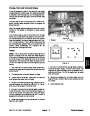
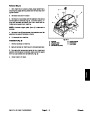
The charge pump (P2) is a fixed displacement gerotor
pump that is driven directly off the traction pump (P1). It
has sufficient output to handle intermittent operation of
the lift cylinder under load. The implement relief valve
(R1) in the charge circuit allows high enough pressure
(1100
PSI / 75.9 bar) to operate the lift cylinder with at-
tachments, and protects the charge pump while using
the lift circuit to raise or lower the attachment.
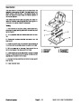
An adjustable detent plate allows the lift lever to be
placed in a float position. When in float, the lift control
valve allows the attachment to follow ground contours
during operation (Fig. 6).
When the lift control valve is in the neutral position, fluid
flow from the charge pump is bypassed around the lift
cylinder through the lift valve. Fluid returns to the tank as
a normal part of the charge and bleed off circuits.
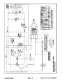
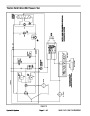
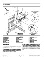
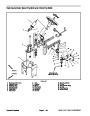
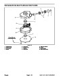
FROM STEERING
CONTROL VALVE
TO OIL
FILTER
LIFT VALVE
(LOWER POSITION)
LOWER POSITION
THIS SYMBOL INDICATES
THAT CHECK VALVE IS
OPENED BY SPOOL CAM PIN
REAR LIFT CYLINDER
(EXTENDING)
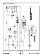
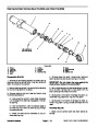
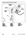
FROM STEERING
CONTROL VALVE
TO OIL
FILTER
LIFT VALVE
(FLOAT POSITION)
FLOAT POSITION
THIS SYMBOL INDICATES
THAT CHECK VALVE IS
OPENED BY SPOOL CAM PIN
REAR LIFT CYLINDER
(FLOATING)
Figure 6
Sand Pro & Infield Pro 3040/5040
Page 4 – 13
Hydraulic System
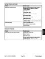
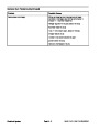
| Categories | Lawn Mower Manual, Sprinkler and Irrigation Manuals, Toro Sprinkler and Irrigation Manuals |
|---|---|
| Tags | Toro 3040, Toro 5040 |
| Download File |
|
| Document Type | Service Manual |
| Language | English |
| Product Brand | Toro. Customer Service Representatives are available by phone:
Monday - Friday 7:30 a.m. to 9:00 p.m. (CDT) - Saturday 8:00 a.m. to 8:00 p.m. (CDT) - Sunday 10:00 a.m. to 8:00 p.m. (CDT)
Canada 1-888-225-4886 USA 1-888-384-9939, Lawn Mower |
| Document File Type | |
| Publisher | toro.com |
| Wikipedia's Page | Toro Company |
| Copyright | Attribution Non-commercial |
(0 votes, average: 0 out of 5)