


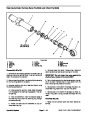


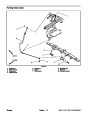
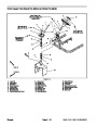


17.If
mark fitting location and orientation to allow correct as-
sembly. Remove fittings from hydrostat.
hydraulic fittings are to be removed from hydrostat,
4. Remove plugs and caps placed in hoses and fittings
during hydrostat removal.
5.
Position new o–rings and correctly connect hydraulic
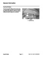
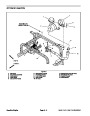
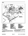
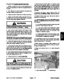
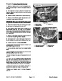
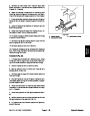
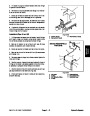
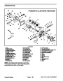
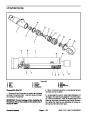
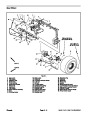
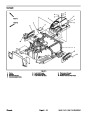
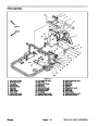
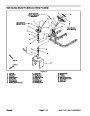
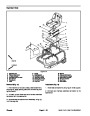
Installation (Fig. 47)
lines to fittings on hydrostat. Use labels placed during
the removal process to properly install hoses to hydros-
tat.
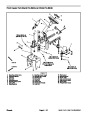
1.
with new o–rings to hydrostat using marks made during
the removal process to properly orientate fittings.
If fittings were removed from hydrostat, install fittings
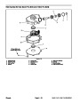
6. Install oil cooler to machine (see Oil Cooler Installa-
tion in this section).
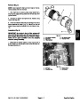
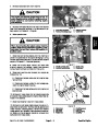
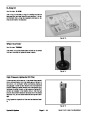
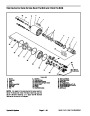
2.
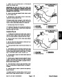
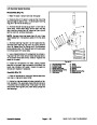
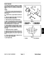
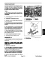
If fan was removed from hydrostat, apply antiseize
lubricant to bore of fan hub. Position key in hydrostat
shaft slot and slide fan hub fully onto shaft. Make sure
that fan hub shoulder bottoms on shaft. Apply Loctite
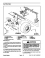
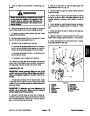
7. Secure traction rod to pump lever with cap screw,
lock nut and flat washer.
8.
Connect traction neutral switch connector to ma-
242
(or equivalent) to threads of fan hub set screws.
chine wire harness.
Torque both set screws from 90 to 110 in–lb (10.2 to 12.4
N–m) to secure fan to the hydrostat shaft.
9.
Install hydraulic oil filter (see Operator’s Manual).
hydraulic tank with correct hydraulic oil (see Op-
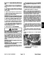
IMPORTANT: Make sure not to damage the hydros-
tat, hydrostat coupling, fuel and hydraulic lines,
electrical harness or other parts while installing the
hydrostat to the machine.
10.Fill
erator’s Manual).
11.
Operate machine functions slowly until air is out of
system (see Charge Hydraulic System in this section).
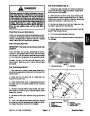
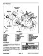
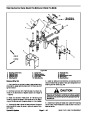
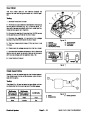
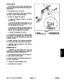
3.
Install hydrostat to machine as follows:
12.Check
ator’s Manual).
and adjust traction neutral position (see Oper-
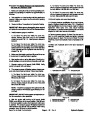
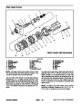
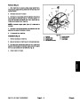
A. Apply antiseize lubricant to bore of pump hub.
Place square key into slot on the hydrostat shaft.
13.Check
tors Manual).
and adjust traction neutral switch (see Opera-
B. Align hydrostat shaft to pump hub. Slide hydros-
tat toward the rear of machine until hydrostat flange
holes align with holes in engine support. Take care
not to damage the hydrostat coupling.
14.Check
Assembly in this section). Adjust if necessary.
traction rod adjustment (see Pump Control
C. Install two (2) socket head screws and lock nuts
to secure hydrostat to engine support.
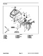
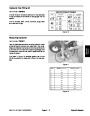
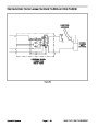
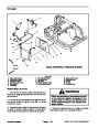
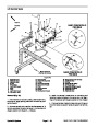
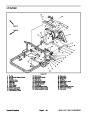
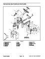
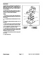
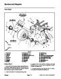
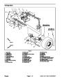
15.Position
center shroud to frame and secure with two
(2)
cap screws and flat washers (Fig. 48).
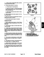
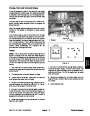
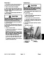
D. Position pump hub on hydrostat shaft so that rub-
ber pump couplings are not distorted. Pump hub
should have a minimum gap of .060” (1.5 mm) to the
hydrostat housing.
E. Apply Loctite 242 (or equivalent) to threads of
pump hub set screws. Tighten both set screws on the
pump hub to secure hub to the hydrostat shaft.
Torque set screws from 90 to 110 in–lb (10.2 to 12.4
N–m).
Hydraulic System
Page 4 – 56
Sand Pro & Infield Pro 3040/5040
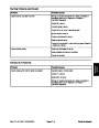
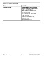
| Categories | Lawn Mower Manual, Sprinkler and Irrigation Manuals, Toro Sprinkler and Irrigation Manuals |
|---|---|
| Tags | Toro 3040, Toro 5040 |
| Download File |
|
| Document Type | Service Manual |
| Language | English |
| Product Brand | Toro. Customer Service Representatives are available by phone:
Monday - Friday 7:30 a.m. to 9:00 p.m. (CDT) - Saturday 8:00 a.m. to 8:00 p.m. (CDT) - Sunday 10:00 a.m. to 8:00 p.m. (CDT)
Canada 1-888-225-4886 USA 1-888-384-9939, Lawn Mower |
| Document File Type | |
| Publisher | toro.com |
| Wikipedia's Page | Toro Company |
| Copyright | Attribution Non-commercial |
(0 votes, average: 0 out of 5)