


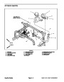
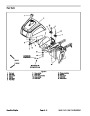
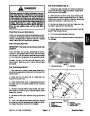


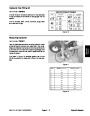
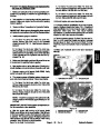
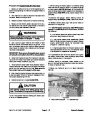
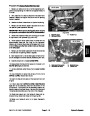


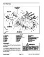
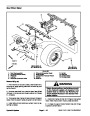

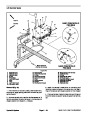


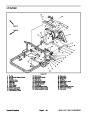
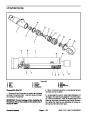
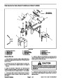

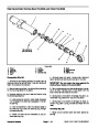

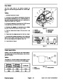


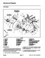

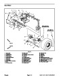
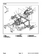
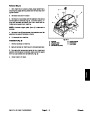
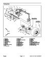
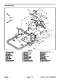
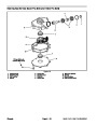
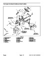


Removal (Fig. 12)
Park machine on a level surface, lower attachment,
stop engine, apply parking brake and remove key from
ignition switch.
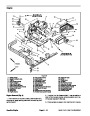
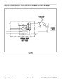
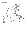
Installation (Fig. 12)
1.
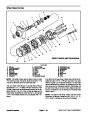
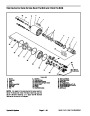
1. If steering box was disassembled to separate steer-
ing box from castor fork shaft, assemble steering box
(see Steering Box Service in this section).
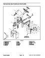
2.
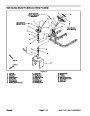
moval in the Service and Repairs section of Chapter 3
Remove fuel tank from machine (see Fuel Tank Re-
2. Thoroughly clean tapered surfaces of castor fork
shaft and sector gear in steering box.
–
Engine).
3. Place woodruff key (item 17) in slot of castor fork
shaft.
3.
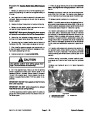
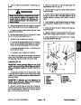
Remove cap screw (item 9) and lock nut (item 19)
that secure steering shaft to steering box.
4.
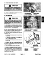
Align slot in steering box sector gear with woodruff
4.
race of bearing (item 8) to steering shaft.
Loosen set screw (item 23) that secures extended
key and slide steering box onto castor fork shaft.
5.
Secure steering box to castor fork with flange nut
5.
steering box input shaft. Position steering wheel and
shaft assembly away from steering box.
Lift on steering wheel to separate steering shaft from
(item 10). Torque flange nut from 50 to 60 ft–lb (68 to 81
N–m). Fit grommet (item 3) to top of steering box.
6.
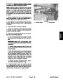
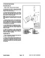
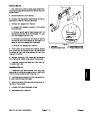
Apply antiseize lubricant to the steering box input
6.
7.
Remove grommet (item 3) from top of steering box.
Loosen and remove flange nut (item 10) that secures
shaft.
7. Position the front wheel straight ahead.
steering box to castor fork shaft.
8. Slide steering shaft assembly onto steering box input
shaft.
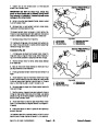
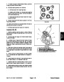
NOTE: The steering box sector gear and castor fork
shaft have tapered shafts that must be loosened before
steering box can be separated from castor fork.
9.
Secure steering shaft to steering box input shaft with
cap screw and lock nut.
8.
one of the following procedures:
Separate steering box from castor fork shaft using
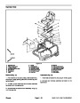
10.Apply
Loctite #242 (or equivalent) to bearing set
screw (item 23). Install and tighten set screw to secure
extended race of bearing (item 8) to steering shaft.
Torque set screw from 90 to 120 in–lb (10.2 to 13.6
N–m).
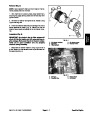
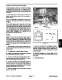
A. Remove cotter pin (item 13) from castor fork
shaft. Carefully loosen slotted hex nut (item 12) to
push the steering box from castor fork shaft. Lift
steering box from machine.
11.
Install fuel tank to machine (see Fuel Tank Installa-
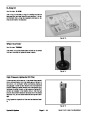
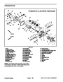
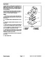
B. Remove eight (8) cap screws that secure steer-
ing plate to steering box cover (see Steering Box
Service in this section). Lift cover from sector gear
and position steering plate away from sector gear.
Use a suitable puller to remove sector gear from cas-
tor fork shaft. Remove steering plate from machine.
tion in the Service and Repairs section of Chapter 3 –
Engine).
9.
Locate and retrieve woodruff key (item 17).
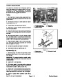
slotted hex nut (item 12) was loosened during
10.If
steering box removal, tighten the slotted hex nut from 15
to 20 in-lb (1.7 to 2.3 N–m). Make sure that the fork does
not have any endplay and it rotates without binding. Se-
cure slotted hex nut to castor fork with cotter pin (item
13).
Sand Pro & Infield Pro 3040/5040
Page 6 – 19
Chassis
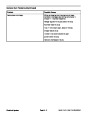
| Categories | Lawn Mower Manual, Sprinkler and Irrigation Manuals, Toro Sprinkler and Irrigation Manuals |
|---|---|
| Tags | Toro 3040, Toro 5040 |
| Download File |
|
| Document Type | Service Manual |
| Language | English |
| Product Brand | Toro. Customer Service Representatives are available by phone:
Monday - Friday 7:30 a.m. to 9:00 p.m. (CDT) - Saturday 8:00 a.m. to 8:00 p.m. (CDT) - Sunday 10:00 a.m. to 8:00 p.m. (CDT)
Canada 1-888-225-4886 USA 1-888-384-9939, Lawn Mower |
| Document File Type | |
| Publisher | toro.com |
| Wikipedia's Page | Toro Company |
| Copyright | Attribution Non-commercial |
(0 votes, average: 0 out of 5)