


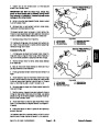


7.
wheel hub to wheel motor.
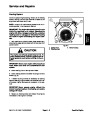
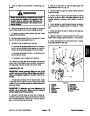
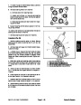
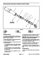
Loosen but do not remove lock nut that secures
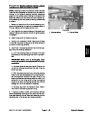
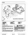
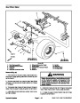
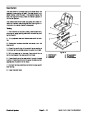
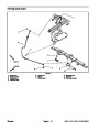
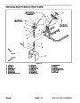
SAND PRO/INFIELD
PRO 3040
3
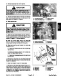
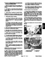
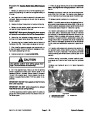
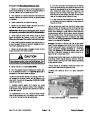
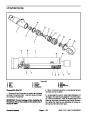
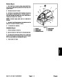
IMPORTANT: DO NOT hit wheel hub, wheel hub
puller or wheel motor with a hammer during wheel
hub removal or installation. Hammering may cause
damage to the wheel motor.
2
1
4
5
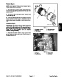
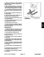
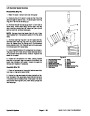
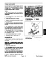
8.
Using hub puller (see Special Tools), loosen wheel
hub from wheel motor.
9.
Remove lock nut and wheel hub from motor shaft.
Locate and retrieve woodruff key.
10.Support
move four (4) cap screws and lock washers that secure
motor to frame. Slide brake bracket from brake bar.
wheel motor to prevent it from falling. Re-
6
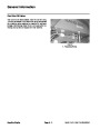
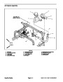
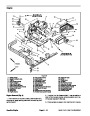
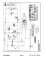
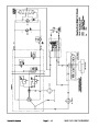
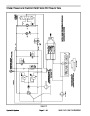
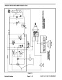
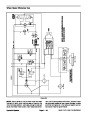
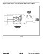
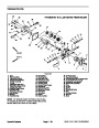
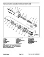
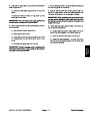
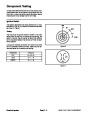
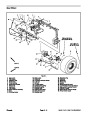
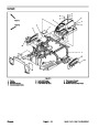
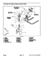
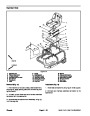
Figure 37
4.
5.
6.
11.
Remove wheel motor from machine.
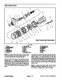
hydraulic fittings are to be removed from wheel mo-
1.
2.
3.
LH rear motor
RH rear motor
Lift control valve
Hydraulic bleed tube
Hydraulic tube
Hydraulic tube
12.If
tor, mark fitting orientation to allow correct assembly.
Remove fittings from motor.
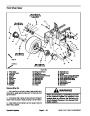
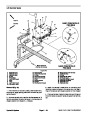
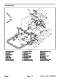
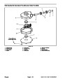
SAND PRO/INFIELD
PRO 5040
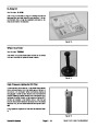
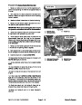
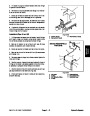
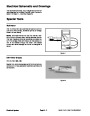
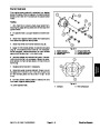
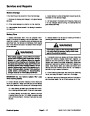
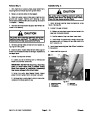
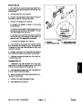
Installation (Fig. 36)
1.
tings with new o–rings to motor using marks made dur-
ing the removal process to properly orientate fittings.
If fittings were removed from wheel motor, install fit-
2
1
2.
onto brake bar.
Position wheel motor to frame. Slide brake bracket
3
4
3.
(4)
Secure motor and brake bracket to frame with four
cap screws and lock washers.
4.
Thoroughly clean wheel motor shaft and wheel hub
taper.
5
5.
Install woodruff key into the wheel motor shaft. Align
wheel hub with woodruff key and brake bar. Slide wheel
hub onto motor shaft. Secure hub with lock nut. Torque
lock nut from 200 to 400 ft–lb (271 to 542 N–m).
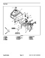
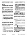
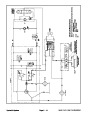
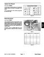
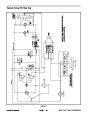
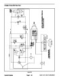
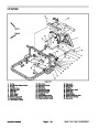
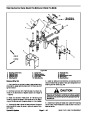
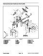
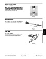
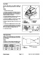
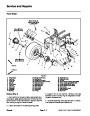
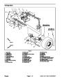
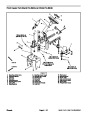
Figure 38
1.
2.
3.
LH rear motor
4. Hydraulic tube
5. Hydraulic tube
RH rear motor
Hydraulic bleed hose
6.
Remove caps or plugs from disconnected hydraulic
lines and fittings.
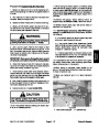
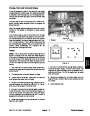
7.
Position new o–rings and connect hydraulic lines to
fittings on rear wheel motor (Fig. 37 and 38). Use labels
placed during the removal process to properly install hy-
draulic lines to wheel motor.
8.
Install rear wheel to machine (see Rear Wheel Instal-
lation in the Service and Repairs section of Chapter 6 –
Chassis).
9.
Check and adjust oil level in hydraulic tank (see Op-
erator’s Manual).
10.Operate
machine functions slowly until air is out of
system (see Charge Hydraulic System in this section).
Sand Pro & Infield Pro 3040/5040
Page 4 – 45
Hydraulic System
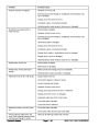
| Categories | Lawn Mower Manual, Sprinkler and Irrigation Manuals, Toro Sprinkler and Irrigation Manuals |
|---|---|
| Tags | Toro 3040, Toro 5040 |
| Download File |
|
| Document Type | Service Manual |
| Language | English |
| Product Brand | Toro. Customer Service Representatives are available by phone:
Monday - Friday 7:30 a.m. to 9:00 p.m. (CDT) - Saturday 8:00 a.m. to 8:00 p.m. (CDT) - Sunday 10:00 a.m. to 8:00 p.m. (CDT)
Canada 1-888-225-4886 USA 1-888-384-9939, Lawn Mower |
| Document File Type | |
| Publisher | toro.com |
| Wikipedia's Page | Toro Company |
| Copyright | Attribution Non-commercial |
(0 votes, average: 0 out of 5)