


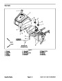
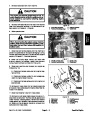


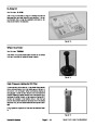


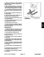
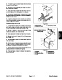
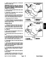

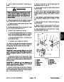


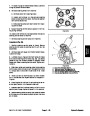


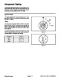
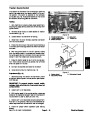


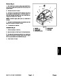
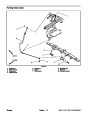
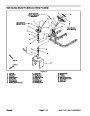
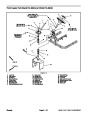


13.Disconnect
control plate and choke control cable from the choke le-
ver (Fig. 11).
throttle control cable from the governor
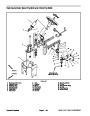
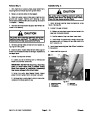
D. Install three (3) cap screws and lock nuts to se-
cure the engine to the engine support. Do not fully
tighten lock nuts.
14.Disconnect
starter motor.
red positive cable (solenoid) from the
E. Position lock washer and negative battery cable
to the engine. Lock washer should be positioned be-
tween engine and ground cable. Install fourth cap
screw up through engine support, engine, lock wash-
er and ground cable and then install lock nut. Do not
fully tighten lock nut.
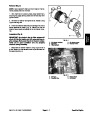
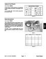
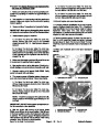
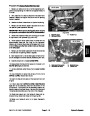
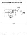
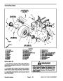
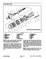
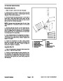
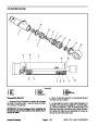
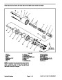
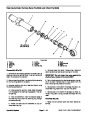
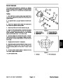
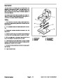
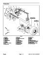
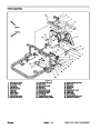
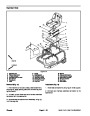
15.Loosen
two (2) set screws on the engine hub to allow
hub removal from the engine stub shaft (Fig. 12).
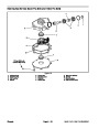
16.Remove
lock nut and cap screw securing engine and
negative battery cable to the engine support. Locate and
retrieve lock washer (item 14). Position cable away from
engine.
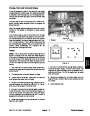
F. Rotate engine crankshaft by hand and check for
deflection of pump couplers that would indicate mis-
alignment between engine and hydrostat. Position
engine on engine support to best align the coupling
assembly.
17.Remove
remaining three (3) lock nuts and cap
screws that secure the engine to the engine support.
G. Tighten four (4) cap screws and lock nuts to se-
cure engine to machine.
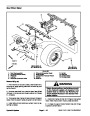
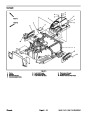
IMPORTANT: Make sure not to damage the engine,
fuel lines, hydraulic lines, electrical harness or oth-
er parts while removing the engine from the ma-
chine.
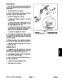
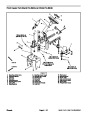
4.
Position engine hub on engine stub shaft so that rub-
ber pump drive couplings are not distorted. Apply Loctite
(or equivalent) to threads of engine hub set
#242
18.Remove
engine from machine as follows:
screws. Tighten both set screws on the engine hub to
secure hub to the engine stub shaft (Fig. 12). Torque set
screws from 90 to 110 in–lb (10.2 to 12.4 N–m).
A. Slide engine toward the rear of machine to re-
move engine stub shaft from engine hub. Take care
not to damage the hydrostat coupling.
5.
Connect throttle control cable to the governor control
plate and choke control cable to the choke lever (Fig.
11).
B. Once the engine stub shaft is clear of the engine
hub, remove engine from the rear of the machine.
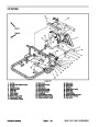
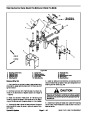
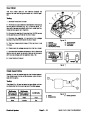
6.
7.
Connect positive cable (solenoid) to starter motor.
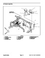
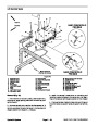
Connect machine wire harness leads to engine as
C. Locate and retrieve square key from the engine
stub shaft.
follows (Fig. 10):
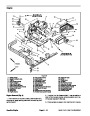
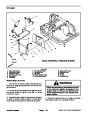
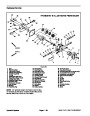
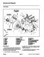
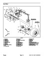
Engine Installation (Fig. 9)
A. Connect harness violet wire to the engine mag-
neto terminal.
1.
2.
during maintenance or rebuilding are properly installed
to the engine.
Position machine on a level surface.
Make sure that all parts removed from the engine
B. Connect harness fusible link to voltage regulator
on engine blower housing.
C. Connect harness yellow wire to engine fuel sole-
noid lead.
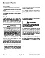
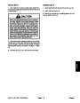
IMPORTANT: Make sure not to damage the engine,
fuel lines, hydraulic lines, electrical harness or oth-
er parts while installing the engine.
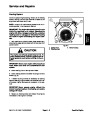
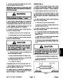
CAUTION
3.
Install engine to machine as follows:
A. Apply antiseize lubricant to bore of engine hub.
Place square key into slot on the engine stub shaft.
When connecting the battery cables to the bat-
tery, make sure to attach the positive (+) battery
cable first and then attach the negative (–) bat-
tery cable.
B. Position engine onto engine support from the rear
of the machine.
C. Align engine stub shaft to engine hub. Slide en-
gine toward the front of machine until mounting holes
in engine align with holes in engine support. Take
care not to damage the hydrostat coupling.
8.
tery Service in the Service and Repairs section of Chap-
ter 5 – Electrical Systems).
Install and connect battery to the machine (see Bat-
Gasoline Engine
Page 3 – 12
Sand Pro & Infield Pro 3040/5040
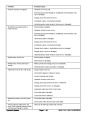
| Categories | Lawn Mower Manual, Sprinkler and Irrigation Manuals, Toro Sprinkler and Irrigation Manuals |
|---|---|
| Tags | Toro 3040, Toro 5040 |
| Download File |
|
| Document Type | Service Manual |
| Language | English |
| Product Brand | Toro. Customer Service Representatives are available by phone:
Monday - Friday 7:30 a.m. to 9:00 p.m. (CDT) - Saturday 8:00 a.m. to 8:00 p.m. (CDT) - Sunday 10:00 a.m. to 8:00 p.m. (CDT)
Canada 1-888-225-4886 USA 1-888-384-9939, Lawn Mower |
| Document File Type | |
| Publisher | toro.com |
| Wikipedia's Page | Toro Company |
| Copyright | Attribution Non-commercial |
(0 votes, average: 0 out of 5)