


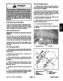


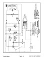


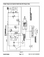
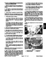
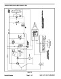
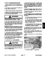
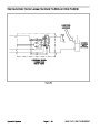


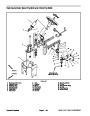

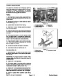


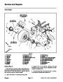
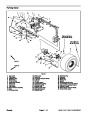
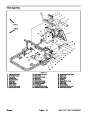
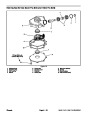


Traction Circuit
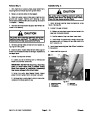
Forward
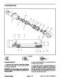
The left rear wheel motor bleeds off a small amount of
hydraulic fluid for cooling of the closed loop traction cir-
cuit. This bleed off happens in the forward direction only.
The high pressure side of the motor forces a shuttle
spool to shift against a spring. The pressure drop across
the motor causes a small amount of fluid to bleed off
through a fixed orifice on the low pressure side of the
motor and then through the shuttle spool. This bleed off
returns to the tank through the lift circuit and oil cooler.
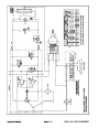
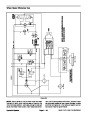
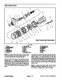
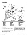
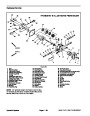
The traction circuit of the hydraulic system consists of a
hydrostat connected in a closed loop circuit to three or-
bital vane wheel motors. Hydraulic fluid losses are de-
signed to occur from case drain leakage of the traction
pump (P1) and bleed off from the left rear wheel motor
(M1). These losses are replenished by the charge pump
(P2), which is integral to the hydrostat.
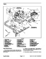
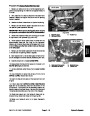
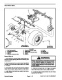
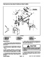
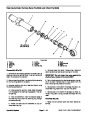
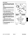
The engine drives traction pump (P1) directly through a
coupling. The traction pump is a variable displacement
piston pump. The traction pedal connects through a link-
age to the trunnion shaft and swash plate of the pump.
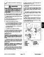
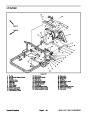
With the engine running and the traction pedal in the
neutral position, P1 supplies no flow to the wheel mo-
tors. When the traction pedal is pressed to the forward
position, the linkage from the pedal positions the swash
plate in the traction pump so oil flows out port B (right
side of pump). Oil flow out of port B goes to the wheel
motors and turns them in the forward direction. The oil
flow goes through the front motor first and then through
the left and right rear wheel motors. Oil flowing out of the
rear wheel motors returns to port A (left side of pump) of
the hydrostat and is continuously pumped out of port B.
Traction relief valve (R3) limits forward traction circuit
pressure to 3200 PSI (220.7 bar).
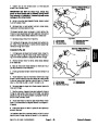
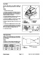
The front wheel motor has a check valve across its ports
that allows the motor to over run during tight turns in the
forward direction.
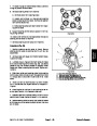
The acceleration valves in the hydrostat reduce the rate
of change in acceleration (jerkiness) when hydrostat
output is increased by the action of the operator. An in-
crease of pressure on the output side of the hydrostat
will by–pass some pump flow to the low pressure side
of the pump. The valve on the high pressure side closes
at a predetermined rate as pressure increases. This
gives the hydrostat a smooth acceleration rate when the
swashplate is stroked rapidly.
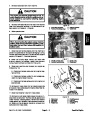
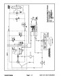
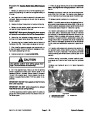
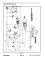
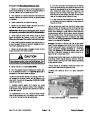
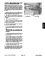
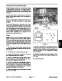
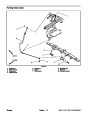
Reverse
The traction circuit operates essentially the same in re-
verse as it does in forward. However, there are a few dif-
ferences in operation.
The hydrostat uses a small amount of hydraulic fluid for
internal lubrication. Fluid is designed to leak across
pump parts into the case drain. This leakage results in
the loss of hydraulic fluid from the closed loop traction
circuit that must be replenished.
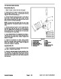
When the traction pedal is pressed to the reverse posi-
tion, the linkage from the pedal positions the traction
pump swash plate so oil flows out of port A (left side of
pump). Oil flow out of port A goes to the wheel motors
and turns them in the reverse direction. The oil flow goes
through the left and right rear wheel motors first and then
is directed to the front wheel motor. Oil by–passes the
front motor in reverse because of the check valve inside
the motor. Oil flowing out of the front wheel motor returns
to port B (right side of pump) of the hydrostat and is con-
tinuously pumped out of port A.
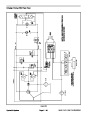
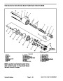
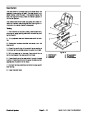
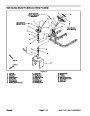
The charge pump (P2) is a fixed displacement gerotor
pump. It is driven directly off the traction pump. The
charge pump replenishes the closed loop traction circuit
with hydraulic fluid from the tank. The charge relief valve
(R2) supplies sufficient head so that charge pump flow
is guided to the low pressure side of the traction circuit
through one of two check valves. Charge pump flow in
excess of traction circuit replenishment requirements is
used for the lift circuit and steering circuit on Sand Pro
The left rear wheel motor does not bleed off any hy-
draulic fluid for cooling of the closed loop traction circuit
in the reverse direction.
5040
and Infield Pro 5040 machines.
Sand Pro & Infield Pro 3040/5040
Page 4 – 11
Hydraulic System
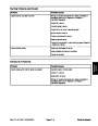
| Categories | Lawn Mower Manual, Sprinkler and Irrigation Manuals, Toro Sprinkler and Irrigation Manuals |
|---|---|
| Tags | Toro 3040, Toro 5040 |
| Download File |
|
| Document Type | Service Manual |
| Language | English |
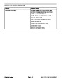
| Product Brand | Toro. Customer Service Representatives are available by phone:
Monday - Friday 7:30 a.m. to 9:00 p.m. (CDT) - Saturday 8:00 a.m. to 8:00 p.m. (CDT) - Sunday 10:00 a.m. to 8:00 p.m. (CDT)
Canada 1-888-225-4886 USA 1-888-384-9939, Lawn Mower |
| Document File Type | |
| Publisher | toro.com |
| Wikipedia's Page | Toro Company |
| Copyright | Attribution Non-commercial |
(0 votes, average: 0 out of 5)