


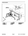
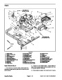


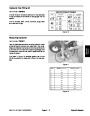
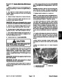
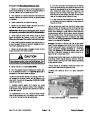


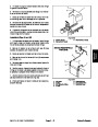
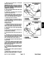


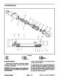


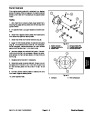
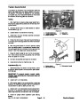


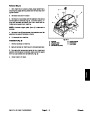
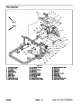


Removal (Fig. 47)
Park machine on a level surface, lower attachment,
stop engine, apply parking brake and remove key from
ignition switch.
2
1
1.
3
2.
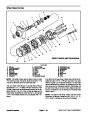
Installing Hydraulic System Components at the begin-
ning of the Service and Repairs section of this chapter.
Read the General Precautions for Removing and
3.
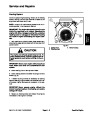
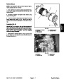
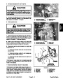
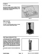
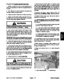
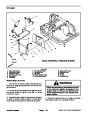
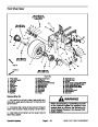
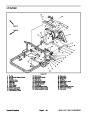
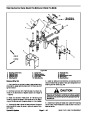
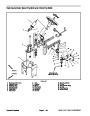
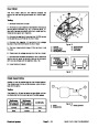
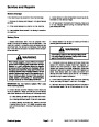
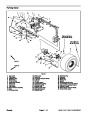
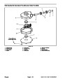
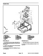
cure center shroud to machine (Fig. 48). Lift center
shroud from frame.
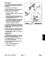
Remove two (2) cap screws and flat washers that se-
4.
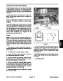
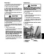
that drain pan is large enough to hold hydraulic tank con-
tents (5 gallons/13.2 liters).
Place drain pan under hydraulic oil filter. Make sure
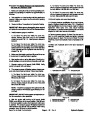
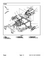
Figure 48
5.
hydraulic tank to drain.
Remove hydraulic oil filter from filter head to allow
1.
2.
Center shroud
Cap screw (2 used)
3.
Flat washer (2 used)
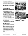
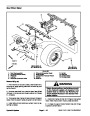
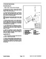
6.
Remove cap screw, lock nut and flat washer that se-
cures traction rod to pump lever.
SAND PRO/INFIELD
PRO 5040
7.
Disconnect traction neutral switch connector from
machine wire harness.
8.
Remove oil cooler from machine (see Oil Cooler Re-
moval in this section).
1
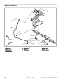
9.
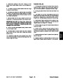
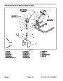
sembly purposes. Thoroughly clean hydraulic hose and
tube ends prior to disconnecting the hoses and tubes.
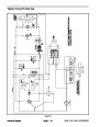
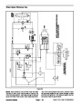
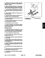
Label all hydraulic connections at hydrostat for as-
2
8
3
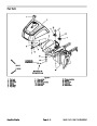
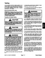
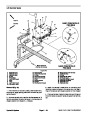
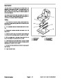
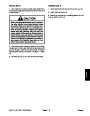
CAUTION
6
6
4
7
Operate all hydraulic controls to relieve system
pressure and avoid injury from pressurized hy-
draulic oil.
5
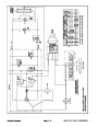
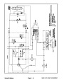
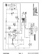
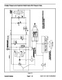
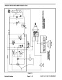
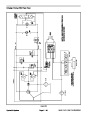
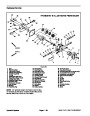
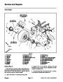
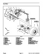
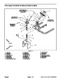
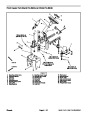
Figure 49
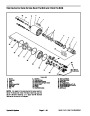
1.
2.
3.
4.
Hydrostat
5.
6.
7.
8.
Hydraulic hose
O–ring
Hydraulic Tee fitting
Hydraulic hose
10.Disconnect
Allow hoses to drain into a suitable container.
hydraulic lines from fittings on hydrostat.
O–ring
90o hydraulic fitting
Hydraulic hose
11.
to prevent contamination.
Put caps or plugs on disconnected lines and fittings
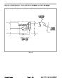
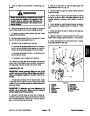
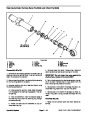
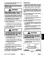
15.Remove
hydrostat from machine as follows:
A. Slide hydrostat toward the front of machine to re-
move hydrostat shaft from pump hub. Take care not
to damage the hydrostat coupling.
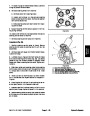
12.Loosen
hub removal from the hydrostat shaft.
two (2) set screws on the pump hub to allow
13.Support
moval.
hydrostat to prevent it from falling during re-
B. Once the hydrostat shaft is clear of the pump hub,
remove hydrostat from the machine.
14.Remove
that secure hydrostat to engine support.
two (2) socket head screws and lock nuts
C. Locate and retrieve square key from the hydros-
tat shaft.
IMPORTANT: Make sure not to damage the hydros-
tat, hydrostat coupling, fuel and hydraulic lines,
electrical harness or other parts while removing the
hydrostat from the machine.
16.If
necessary, loosen two (2) set screws that secure
fan hub to hydrostat shaft. Remove fan and fan hub from
hydrostat. Locate and retrieve square key from shaft.
Sand Pro & Infield Pro 3040/5040
Page 4 – 55
Hydraulic System
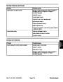
| Categories | Lawn Mower Manual, Sprinkler and Irrigation Manuals, Toro Sprinkler and Irrigation Manuals |
|---|---|
| Tags | Toro 3040, Toro 5040 |
| Download File |
|
| Document Type | Service Manual |
| Language | English |
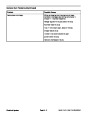
| Product Brand | Toro. Customer Service Representatives are available by phone:
Monday - Friday 7:30 a.m. to 9:00 p.m. (CDT) - Saturday 8:00 a.m. to 8:00 p.m. (CDT) - Sunday 10:00 a.m. to 8:00 p.m. (CDT)
Canada 1-888-225-4886 USA 1-888-384-9939, Lawn Mower |
| Document File Type | |
| Publisher | toro.com |
| Wikipedia's Page | Toro Company |
| Copyright | Attribution Non-commercial |
(0 votes, average: 0 out of 5)