


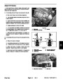


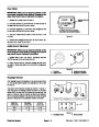


Starter/Generator & Voltage Regulator
1.
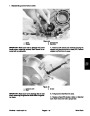
ator’s Manual). Set parking brake.
Place machine in the NEUTRAL position (see Oper-
7. Reconnect green wire connector from the regulator
and test voltage regulator:
2.
electric components by removing the electrical cover.
Raise bed and secure with prop rod. Gain access to
A. Set multimeter to VDC. Connect red (+) probe of
the multimeter into the green wire connection. Con-
nect black (–) probe of the multimeter to a known
good ground.
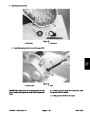
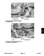
3.
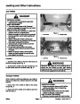
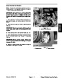
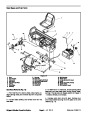
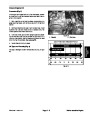
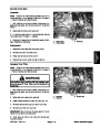
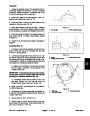
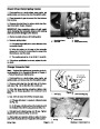
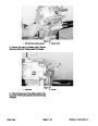
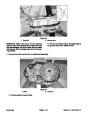
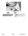
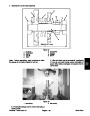
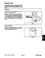
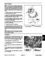
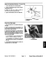
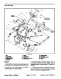
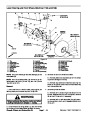
Make sure all wires in the charging circuit are con-
nected correctly and tightly. Note the correct location of
starter/generator cable and voltage regulator wire at the
start/run solenoid (Fig. 10).
B. Start and run the engine at mid–range RPM.
C. The measured voltage should be approximately
2 VDC when battery is charging and 6–8 VDC when
battery is fully charged. This voltage may rise to
12–14 VDC when the accelerator pedal is released
and the engine is coasting to a stop.
4.
vehicle for several minutes so the voltage regulator is
warmed up. Stop engine and turn key to OFF.
Make sure the battery is fully charged. Operate the
5.
Test charging circuit:
D. If measured voltage is incorrect, stop engine and
replace voltage regulator. Retest charging circuit
(Step 5 above).
A. Set multimeter to VDC. Connect red (+) probe of
the multimeter to the positive (+) battery post. Con-
nect black (–) probe of the multimeter to the negative
(–)
post of the battery.
8. Stop engine and remove multimeter leads.
B. Start and run the engine at mid–range RPM.
4
C. Battery voltage should rise to approximately 14.5
VDC identifying a correctly operating charging cir-
cuit. If the battery has a low charge, this may take a
few minutes.
5
2
D. Stop engine and turn key to OFF.
6
6.
If battery voltage did not rise to 14.5 VDC, test start-
er/generator:
3
1
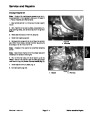
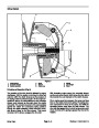
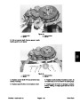
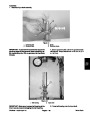
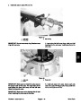
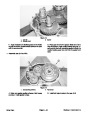
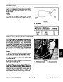
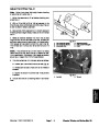
A. Disconnect green wire connector from voltage
regulator (Fig. 10). Connect disconnected green
wire lead from starter/generator to ground with a
jumper lead.
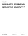
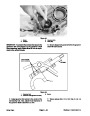
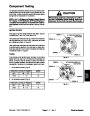
Figure 10
4.
5.
6.
1.
2.
3.
Start/run solenoid
Main contact post
Voltage regulator
Cable to starter/gen.
Wire to voltage regulator
Green wire connector
B. Set multimeter to VDC. Connect red (+) probe of
the multimeter to the positive (+) battery post. Con-
nect black (–) probe of the multimeter to the negative
(–)
post of the battery.
4
3
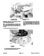
IMPORTANT: Run engine only long enough to get
battery voltage reading and not for more than 15
seconds.
C. Start and run engine at mid–range RPM.
2
D. Battery voltage should rise steadily to approxi-
mately 18 VDC identifying a correctly operating start-
er/generator. An incorrect reading indicates the need
for starter/generator repair.
1
E. Stop engine and turn key to OFF.
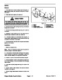
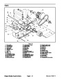
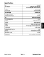
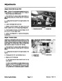
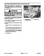
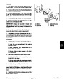
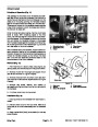
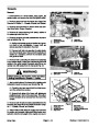
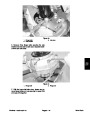
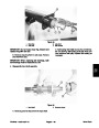
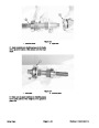
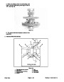
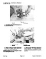
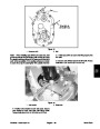
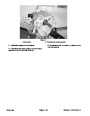
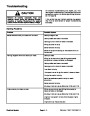
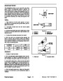
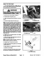
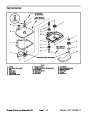
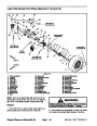
Figure 11
1.
2.
Terminal A1
Terminal A2
3.
4.
Terminal F1 location
Terminal DF location
Electrical System
Page 6 – 10
Workman 1100/1110/2100/2110
| Categories | Lawn Mower Manual, Sprinkler and Irrigation Manuals, Toro Sprinkler and Irrigation Manuals |
|---|---|
| Tags | Toro Workman 1100, Toro Workman 1110, Toro Workman 2100, Toro Workman 2110 |
| Download File |
|
| Document Type | Catalog |
| Language | English |
| Product Brand | Toro. Customer Service Representatives are available by phone:
Monday - Friday 7:30 a.m. to 9:00 p.m. (CDT) - Saturday 8:00 a.m. to 8:00 p.m. (CDT) - Sunday 10:00 a.m. to 8:00 p.m. (CDT)
Canada 1-888-225-4886 USA 1-888-384-9939, Lawn Mower |
| Document File Type | |
| Publisher | toro.com |
| Wikipedia's Page | Toro Company |
| Copyright | Attribution Non-commercial |
(0 votes, average: 0 out of 5)