


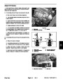
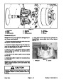


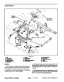


IMPORTANT: Do not remove field coils unless they
are to be replaced.
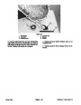
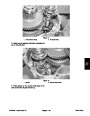
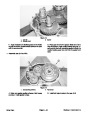
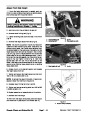
I. Position commutator end cover carefully to the
commutator and yoke. Align end cover to the yoke
with the locating pin.
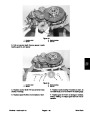
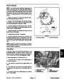
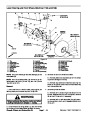
10.To
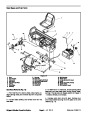
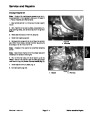
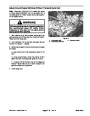
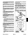
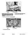
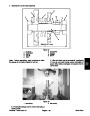
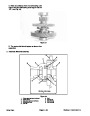
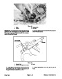
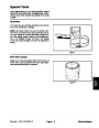
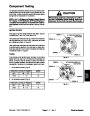
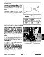
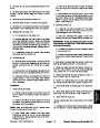
remove field coils (Fig. 27):
J. Secure both end covers to the yoke with both
through bolts and flat washers. Torque bolts from
A. Remove nuts from threaded terminal, and slide
insulator and terminal out of yoke.
95.5
to 104 in–lbs (10.8 to 11.8 N–m).
B. Remove four pole piece screws and pole sets
from the yoke. Remove field coils from the yoke.
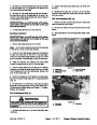
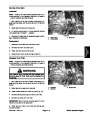
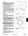
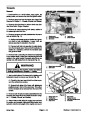
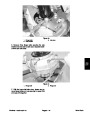
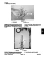
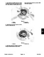
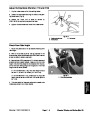
K. Slide brushes into holders. Secure brushes by
positioning brush springs into the notch at the end of
the brushes (Fig. 25).
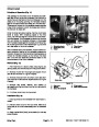
11.
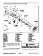
Assemble starter/generator as follows:
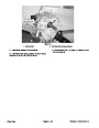
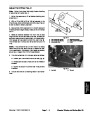
L. Install brush covers to the commutator end cover.
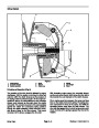
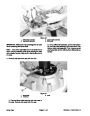
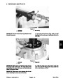
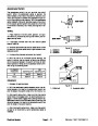
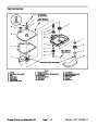
A. Position field coil into yoke. Make sure both insu-
lators that look similar go into the slots marked F1
and F2. The different looking insulator goes into the
slot marked DF. Seat insulators into slots (Fig. 27).
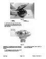
M. Position spacer and woodruff key onto the shaft.
Place pulley onto the shaft.
N. Secure pulley to the shaft with spring washer and
nut. Torque nut from 15 to 25 ft–lb (20 to 34 N–m).
IMPORTANT: Make sure field coil terminal wire will
not make contact with the armature.
9
ft–lb
N–m)
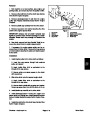
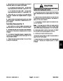
B. Install terminals through wire connectors and in-
sulators. Secure flat washer, lock washer, and nut
onto each terminal. Torque nuts from 43 to 52 in–lb
5
(12
43
to 52 in–lb
(4.9
to 5.9 N–m) (Fig. 27).
(4.9 to 5.9 N–m)
7
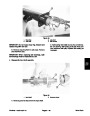
C. Position all four pole pieces into the yoke. Secure
pole pieces with set screws. Torque screws to 9 ft–lb
2
(12
N–m) (Fig. 27).
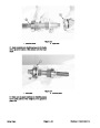
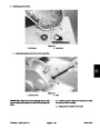
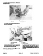
D. Position bearing retainer onto the output shaft of
the armature. Press new ball bearing onto the shaft
being careful not to damage the retainer.
4
6
E. Press new ball bearing onto the commutator end
of the armature shaft.
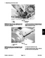
F. Position front end cover onto the output shaft. Se-
cure bearing retainer to the end cover with flat wash-
ers, lock washers, and screws. Torque screws from
1
35
to 43 in–lb (4.0 to 4.9 N–m).
3
G. Position armature carefully into the yoke. Make
sure not to damage field coils. Align front end cover
to the yoke with the locating pin.
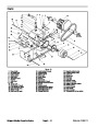
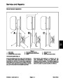
Figure 27
1.
2.
3.
4.
Field coils
5.
6.
7.
Set screw
Pole piece
Yoke
Nut and washers
Threaded terminal
Insulator
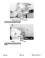
IMPORTANT: When installing the commutator end
cover, make sure brushes do not contact the com-
mutator. Damage to the brushes may result.
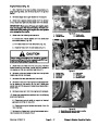
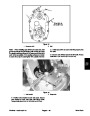
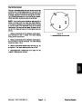
H. Lift brush springs from the notch at the end of the
brushes while pulling the brushes out. Allow springs
to hold brushes out from the center (Fig. 23).
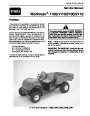
Workman 1100/1110/2100/2110
Page 6 – 21
Electrical System
| Categories | Lawn Mower Manual, Sprinkler and Irrigation Manuals, Toro Sprinkler and Irrigation Manuals |
|---|---|
| Tags | Toro Workman 1100, Toro Workman 1110, Toro Workman 2100, Toro Workman 2110 |
| Download File |
|
| Document Type | Catalog |
| Language | English |
| Product Brand | Toro. Customer Service Representatives are available by phone:
Monday - Friday 7:30 a.m. to 9:00 p.m. (CDT) - Saturday 8:00 a.m. to 8:00 p.m. (CDT) - Sunday 10:00 a.m. to 8:00 p.m. (CDT)
Canada 1-888-225-4886 USA 1-888-384-9939, Lawn Mower |
| Document File Type | |
| Publisher | toro.com |
| Wikipedia's Page | Toro Company |
| Copyright | Attribution Non-commercial |
(0 votes, average: 0 out of 5)