


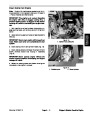
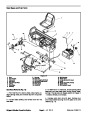
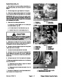
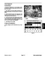
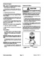


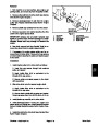
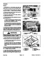
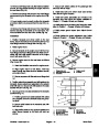
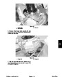
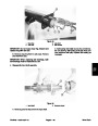


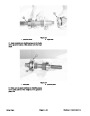
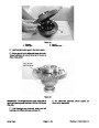
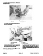


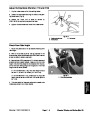
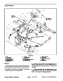
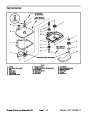
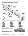


Removal (Fig. 18)
Park machine on a level surface, stop engine, set
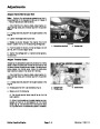
5. Torque castle nut to the shaft between 120 to 200 ft–
lb (163 to 271 N–m) while aligning nut to hole in shaft.
Install cotter pin.
1.
parking brake, and remove key from the ignition switch.
6.
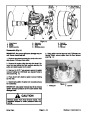
Slide brake drum onto wheel hub.
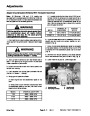
WARNING
7. Position wheel assembly to the machine with valve
stem facing out and secure with five lug nuts. Torque lug
nuts in a criss–cross pattern from 45 to 65 ft–lb (61 to 88
N–m).
Before jacking up the machine, review and follow
Jacking Instructions in Chapter 1 – Safety.
8.
Lower machine to ground.
2.
the ground using a jack, and place blocks beneath the
frame under the axle tube.
Chock wheels not being jacked up. Lift rear wheel off
CAUTION
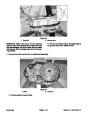
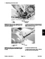
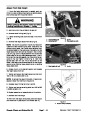
3.
from the wheel hub.
Remove five lug nuts, tire and wheel, and brake drum
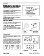
After servicing the brakes, always check the
brakes in a wide open, level area that is free of
other persons and obstructions.
4.
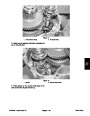
Remove cotter pin from the castle nut and transaxle
shaft. Remove castle nut, lock washer, and spacer from
the shaft. Remove the wheel hub from the shaft.
9.
Check and adjust brakes (see Brake Adjustment).
NOTE: The brake assembly can be removed from the
transaxle shaft for disassembly.
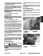
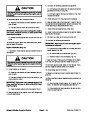
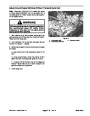
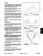
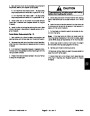
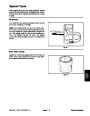
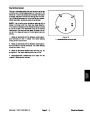
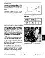
Burnish Brake Shoes
Sintered metal linings may not provide maximum brake
stopping distance after brake shoes are replaced. It is
necessary to burnish new brake shoe linings.
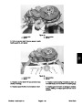
5.
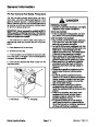
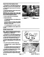
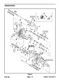
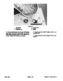
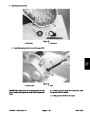
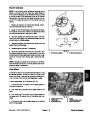
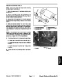
Remove brake assembly as follows:
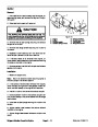
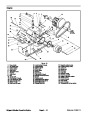
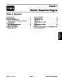
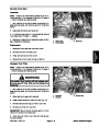
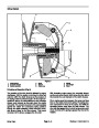
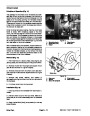
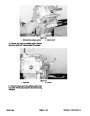
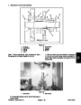
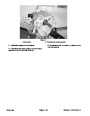
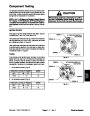
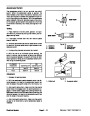
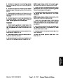
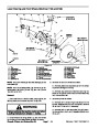
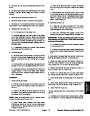
A. Remove cotter pin and clevis pin securing the
cable bracket to the actuator lever (Fig. 19).
IMPORTANT:Do not drive machine with the brakes
applied. The brake shoe linings will overheat.
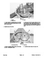
B. Remove four cap screws and flanged lock nuts
securing the anchor plate of the brake assembly to
the transaxle. Remove brake assembly from the
transaxle.
IMPORTANT:Do not allow the brakes to lock up. Al-
low brakes to cool between applications.
1.
about 200 ft (60 m) intervals while traveling at 10 to 15
mph (16 to 24 KPH).
Drive machine while making 6 to 7 normal stops at
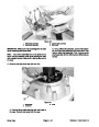
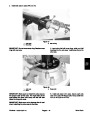
Installation (Fig. 18)
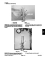
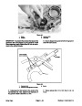
IMPORTANT:Brake actuator levers must be posi-
tioned above the transaxle mount. When positioned
correctly, actuator lever will point toward the rear of
the axle (Fig. 19).
2.
in the reverse direction. This will self adjust the clear-
ance between the brake shoe and drum.
Make several normal stops with the machine going
1.
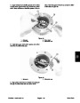
If brake assembly was removed from axle, position
brake assembly to the transaxle. Secure backing plate
of the brake assembly to the transaxle with four cap
screws and flanged lock nuts. Torque screws to 20 ft–lb
4
1
(27
N–m).
2.
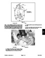
Secure cable bracket to the actuator lever with clevis
pin and cotter pin (Fig. 19).
IMPORTANT:Do not get antiseize lubricant onto
brake shoes.
3
3.
Apply light coat of antiseize lubricant to the transaxle
2
shaft splines.
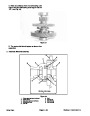
Figure 19
3.
4.
4.
washer, and castle nut.
Secure wheel hub to the shaft with spacer, lock
1.
2.
Cotter pin
Clevis pin
Brake cable bracket
Actuator lever
Workman 1100/1110/2100/2110
Page 7 – 27
Chassis, Wheels, and Brakes (Rev. B)
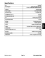
| Categories | Lawn Mower Manual, Sprinkler and Irrigation Manuals, Toro Sprinkler and Irrigation Manuals |
|---|---|
| Tags | Toro Workman 1100, Toro Workman 1110, Toro Workman 2100, Toro Workman 2110 |
| Download File |
|
| Document Type | Catalog |
| Language | English |
| Product Brand | Toro. Customer Service Representatives are available by phone:
Monday - Friday 7:30 a.m. to 9:00 p.m. (CDT) - Saturday 8:00 a.m. to 8:00 p.m. (CDT) - Sunday 10:00 a.m. to 8:00 p.m. (CDT)
Canada 1-888-225-4886 USA 1-888-384-9939, Lawn Mower |
| Document File Type | |
| Publisher | toro.com |
| Wikipedia's Page | Toro Company |
| Copyright | Attribution Non-commercial |
(0 votes, average: 0 out of 5)