


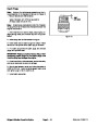

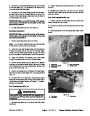
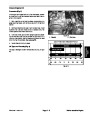
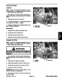


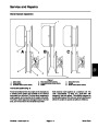
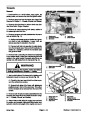


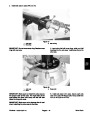


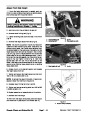


10.Remove
mounts, and cap screws securing the engine mount to
the rear frame (Fig. 23).
both flange lock nuts, flat washers, isolation
7. Secure both battery cables to the passenger side
axle tube with tie wraps.
8.
Install drive belt to the driven clutch (see Service
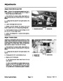
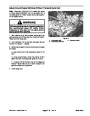
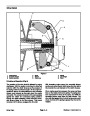
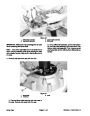
11.
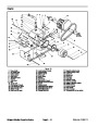
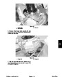
Remove four flange lock nuts and hex head flange
Drive Belt in Engine Chapter).
screws securing the transaxle to the engine mount (Fig.
24).
9.
transaxle (see Rear Wheel and Brake Installation in
Chapter 7 – Chassis, Wheels, and Brakes).
Install both brake assemblies and wheels to the
12.Lower
engine mount enough to allow the transaxle
and driven clutch to be removed from the rear of the ve-
hicle.
10.Install
lation in Chapter 7 – Chassis, Wheels, and Brakes).
cargo box to the frame (see Cargo Box Instal-
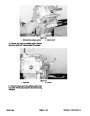
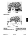
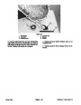
13.Remove
screws securing the transaxle to the rear frame. Re-
move transaxle from the rear of the vehicle (Fig. 23).
four flange lock nuts and hex head flange
11.
Speed).
Verify proper ground speed (see Adjust Ground
12.Check
Brakes in Chapter 7 – Chassis, Wheels, and Brakes).
brakes for proper adjustment (see Adjust
Installation
1.
Position transaxle and driven clutch to the rear
frame. Secure transaxle to the rear frame with four hex
head flange screws and flange lock nuts (Fig. 23).
2.
Raise engine mount.
3
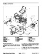
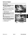
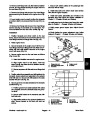
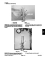
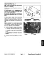
3.
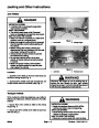
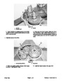
Secure transaxle to the engine mount with four hex
2
5
head flange screws and flange lock nuts. Make sure R–
clamp with both shift cables is secured to the engine
mount with screw (Fig. 24).
4
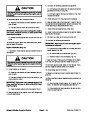
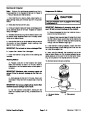
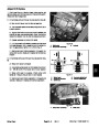
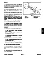
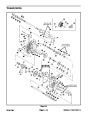
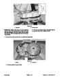
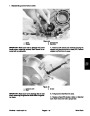
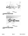
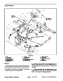
4.
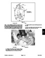
Secure engine mount to the rear frame as follows
(Fig. 23 and 25):
1
A. Attach both isolation mounts to the engine mount.
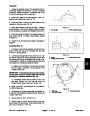
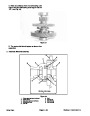
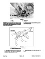
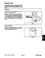
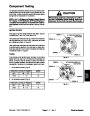
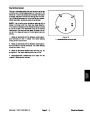
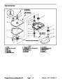
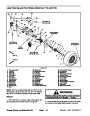
Figure 24
B. Align engine mount to rear frame. Insert cap
screw through rear frame channel, isolation mounts,
and engine mount.
1.
2.
3.
Flange lock nut
Hex head flange screw
Transaxle
4.
5.
Engine mount
R–clamp
C. Secure cap screw with flat washer and flange lock
nut.
5
4
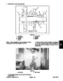
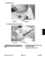
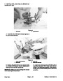
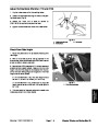
5.
Position select lever assembly and shift cables to the
transaxle. Secure select lever assembly to the selector
shaft with lock nut. Secure both shift cables to the cable
bracket with jam nuts (Fig. 22).
1
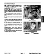
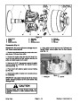
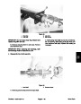
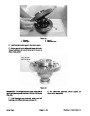
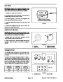
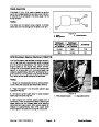
6.
Secure governor and cable brackets to the transaxle
as follows (Fig. 21).
3
2
A. Position governor and cable brackets with cables
as a complete unit to the transaxle case and gover-
nor shaft.
6
B. Secure cable bracket to the transaxle case with
both lock nuts.
7
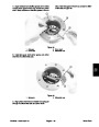
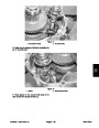
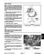
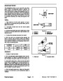
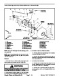
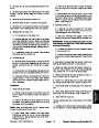
Figure 25
C. Align scribe marks on the governor bracket and
shaft. Secure bracket to the shaft with both set
screws.
1.
2.
3.
4.
Iso mount (top)
5.
6.
7.
Cap screw
Flat washer
Flange lock nut
Iso mount (bottom)
Engine mount
Rear frame channel
Workman 1100/2100/2110
Page 5 – 17
Drive Train
| Categories | Lawn Mower Manual, Sprinkler and Irrigation Manuals, Toro Sprinkler and Irrigation Manuals |
|---|---|
| Tags | Toro Workman 1100, Toro Workman 1110, Toro Workman 2100, Toro Workman 2110 |
| Download File |
|
| Document Type | Catalog |
| Language | English |
| Product Brand | Toro. Customer Service Representatives are available by phone:
Monday - Friday 7:30 a.m. to 9:00 p.m. (CDT) - Saturday 8:00 a.m. to 8:00 p.m. (CDT) - Sunday 10:00 a.m. to 8:00 p.m. (CDT)
Canada 1-888-225-4886 USA 1-888-384-9939, Lawn Mower |
| Document File Type | |
| Publisher | toro.com |
| Wikipedia's Page | Toro Company |
| Copyright | Attribution Non-commercial |
(0 votes, average: 0 out of 5)