


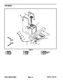
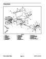
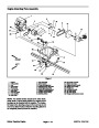
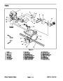


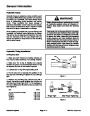


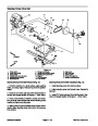

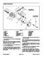


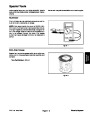


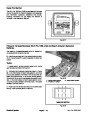


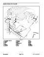
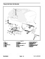


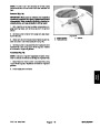
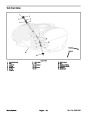
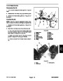
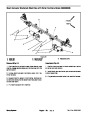
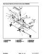
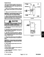

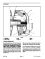


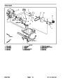
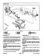
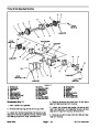


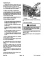
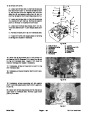
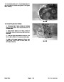


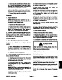
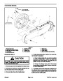


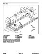
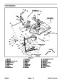
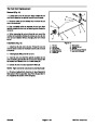
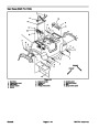


Disassembly (Fig. 8)
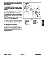
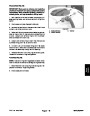
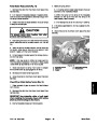
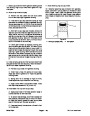
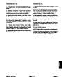
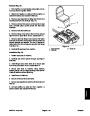
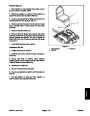
D. Position dust plate and felt seal on both ends of
crankshaft.
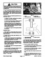
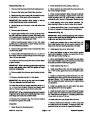
IMPORTANT: Make sure to remove and neutralize
chemicals from pump before disassembly. Wear
protective clothing, chemical resistant gloves, and
eye protection during pump repair.
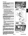
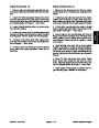
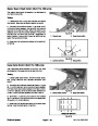
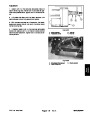
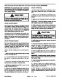
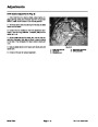
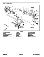
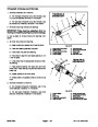
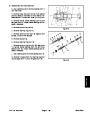
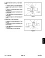
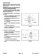
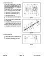
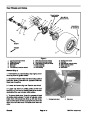
IMPORTANT: If connecting rod position is incor-
rect, pump will not operate properly.
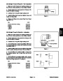
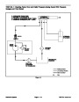
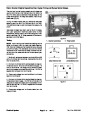
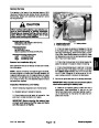
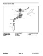
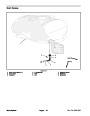
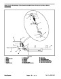
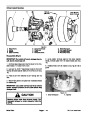
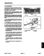
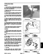
E. Slide crankshaft assembly into pump casing. The
rear connecting rod should be positioned to the left
side and the connecting rod closest to you to the right
side (Fig. 9).
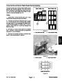
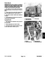
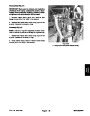
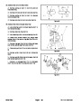
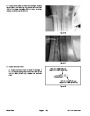
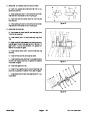
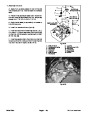
1.
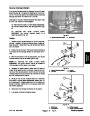
to pump. Separate valve chamber from pump.
Remove two (2) hex bolts that retain valve chamber
2.
Remove inlet and outlet valves and o–rings from
each diaphragm cover. Note orientation of valves. Dis-
card valves and o–rings. Clean valve and o–ring seats
in the valve chambers and diaphragm covers.
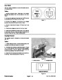
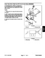
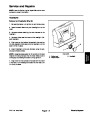
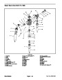
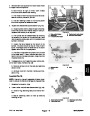
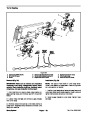
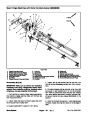
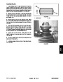
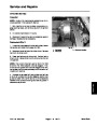
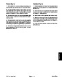
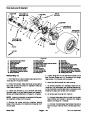
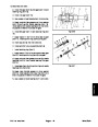
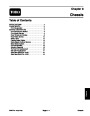
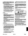
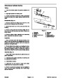
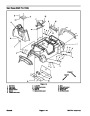
2. Place second pump casing onto assembly. Pump
casing surfaces should mate together.
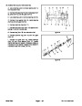
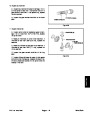
3.
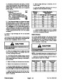
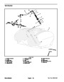
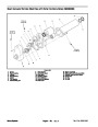
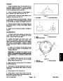
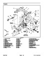
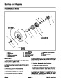
Install three (3) shorter (30 mm) and two (2) longer
3.
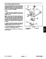
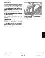
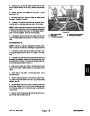
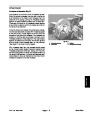
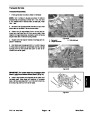
Remove hex bolts and nuts that secure diaphragm
(55 mm) bolts into pump casing assembly (Fig. 10).
Thread hex nuts onto bolts but do not fully tighten.
Check that crankshaft turns freely.
covers to pump. Remove diaphragm covers. Note:
Some pumps may use bolts that thread into the pump
casings to secure diaphragm covers.
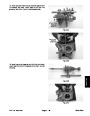
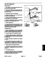
4.
and diaphragm back disc from each connecting rod.
Discard diaphragms.
Remove hex bolt, washer, nylon washer, diaphragm,
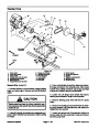
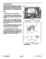
5.
casing halves together. Note location of two (2) longer
hex bolts. Carefully separate pump casing halves.
Remove five (5) hex bolts and nuts that secure pump
2
1
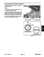
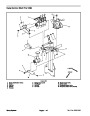
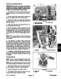
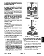
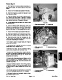
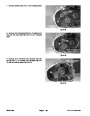
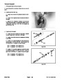
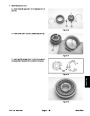
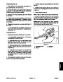
6.
Clean grease from bottom of housing and check con-
dition of bearings on crankshaft. If bearings require re-
placement, remove and disassemble crankshaft:
A. Remove crankshaft assembly from pump casing.
B. Slide felt seal and dust plate from both ends of
crankshaft.
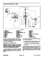
Figure 9
Closest connecting rod (to right side)
Rear connecting rod (to left side)
1.
2.
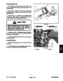
C. Loosen bolt and hex nut that secure connecting
rods to crankshaft. Slide connecting rods from crank-
shaft.
D. Press ball bearings from crankshaft.
1
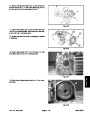
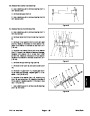
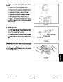
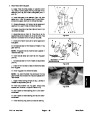
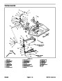
Assembly (Fig. 8)
1.
If disassembled, reassemble crankshaft.
1
A. Hand pack new bearings with #2 general purpose
lithium base grease.
1
B. Pressing on bearing inner race, install two con-
necting rod and two crankshaft ball bearings onto
crankshaft.
2
2
C. Slide connecting rods onto rod bearings. Offsets
of the connecting rods should face each other. Install
hex bolt, flat washers, and hex nut to connecting rod.
Torque hex nuts to 25 ft–lb (34 N–m) to secure con-
necting rod to crankshaft.
Figure 10
1.
Hex bolt (30 mm long)
2.
Hex bolt (55 mm long)
Multi Pro 1200/1250
Spray System
Page 6 – 15
| Categories | Lawn Mower Manual, Sprinkler and Irrigation Manuals, Toro Sprinkler and Irrigation Manuals |
|---|---|
| Tags | Toro Multi Pro 1200, Toro Multi Pro 1250 |
| Download File |
|
| Document Type | Service Manual |
| Language | English |
| Product Brand | Toro. Customer Service Representatives are available by phone:
Monday - Friday 7:30 a.m. to 9:00 p.m. (CDT) - Saturday 8:00 a.m. to 8:00 p.m. (CDT) - Sunday 10:00 a.m. to 8:00 p.m. (CDT)
Canada 1-888-225-4886 USA 1-888-384-9939, Lawn Mower |
| Document File Type | |
| Publisher | toro.com |
| Wikipedia's Page | Toro Company |
| Copyright | Attribution Non-commercial |
(0 votes, average: 0 out of 5)