


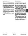

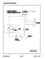


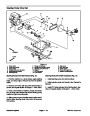

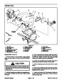


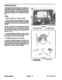
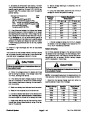


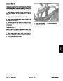
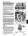


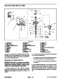


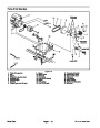

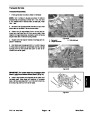


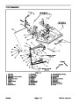


Spray System Operation
The Multi Pro 1200 and 1250 spray systems use a posi-
tive displacement diaphragm pump to move spray solu-
tion from the spray tank to the boom nozzles. The spray
pump is self–priming and has a dry crankcase. The
pump is driven by the pump drive gearbox output shaft
at a speed that is proportional to the ground speed of the
vehicle. The pump is engaged with an electric clutch.
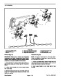
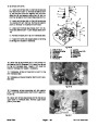
The spray system on the Multi Pro 1250 is controlled
electrically and consists of a main control valve and
three boom control valves. An adjustable boom bypass
valve exists in each of the boom control valves to pre-
vent system pressure changes when a boom section is
shut off. Flow in excess of control valve settings is di-
rected back to the spray tank or used for tank agitation.
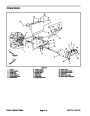
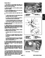
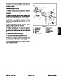
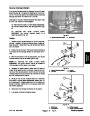
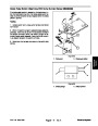
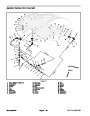
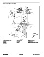
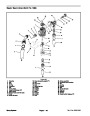
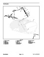
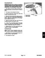
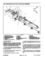
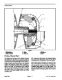
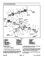
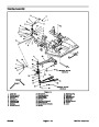
The downward stroke of the pumps’ connecting rods
and diaphragms create suction to allow fluid to be drawn
from the spray tank to the pump through the suction
tube, suction strainer, hoses, and connectors. A suction
dampener placed in the suction line dampens suction
pulses to smooth suction flow. Suction valves positioned
in the pump valve chamber prevent fluid from being
pumped back into the suction line when the connecting
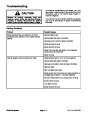
rods change direction. Leaks in the suction line will
cause system problems and often will be indicated by er-
ratic suction line jumping and pump noise.
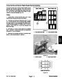
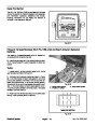
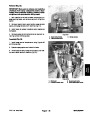
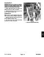
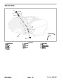
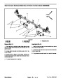
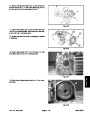
An inline flowmeter in the pressure side of the system di-
rectly before the boom control valves measures flow to
the spray booms. The Spray Pro Monitor displays infor-
mation regarding application rate based on input from
the flowmeter and the ground speed sensor.
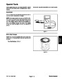
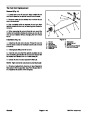
Flow for tank agitation on both the Multi Pro 1200 and
1250
comes from flow that is bypassed by the pressure
control valve. A manual agitation control valve directs
flow to five agitation nozzles in the spray tank.
Battery current for spray system fuses, switches, relays,
and other components is provided by the accessory so-
lenoid when the machine ignition switch is in the RUN
position. For spray system electrical component infor-
mation and test procedures, see Chapter 5 – Electrical
System.
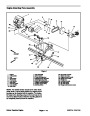
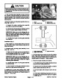
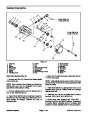
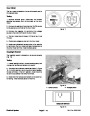
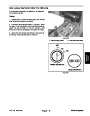
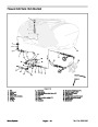
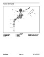
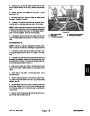
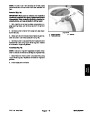
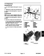
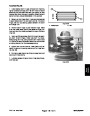
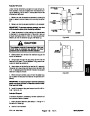
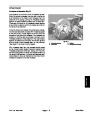
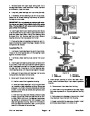
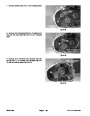
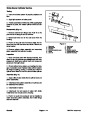
Once to the pump, the fluid is pushed by the upward
stroke of the pumps’ connecting rods and diaphragms
to the pressure side of the spray system through hoses,
connectors, control valves, and spray nozzles. A pres-
sure dampener at the pump outlet smooths system
pressure pulsation. Pressure valves positioned in the
pump head prevent fluid from being drawn back into the
pump. Maximum pressure in the system is limited by a
pressure relief valve located in the tank. A pressure
gauge indicates system pressure.
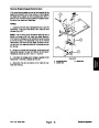
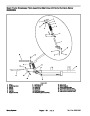
The spray control system on the Multi Pro 1200 consists
of a main on/off valve, a pressure control valve, and
three boom control valves. An adjustable boom bypass
valve exists in each of the boom control valves to pre-
vent system pressure changes when a boom section is
shut off. Flow in excess of control valve settings is di-
rected back to the spray tank or used for tank agitation.
Multi Pro 1200/1250
Spray System
Page 6 – 3
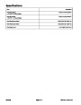
| Categories | Lawn Mower Manual, Sprinkler and Irrigation Manuals, Toro Sprinkler and Irrigation Manuals |
|---|---|
| Tags | Toro Multi Pro 1200, Toro Multi Pro 1250 |
| Download File |
|
| Document Type | Service Manual |
| Language | English |
| Product Brand | Toro. Customer Service Representatives are available by phone:
Monday - Friday 7:30 a.m. to 9:00 p.m. (CDT) - Saturday 8:00 a.m. to 8:00 p.m. (CDT) - Sunday 10:00 a.m. to 8:00 p.m. (CDT)
Canada 1-888-225-4886 USA 1-888-384-9939, Lawn Mower |
| Document File Type | |
| Publisher | toro.com |
| Wikipedia's Page | Toro Company |
| Copyright | Attribution Non-commercial |
(0 votes, average: 0 out of 5)