


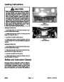


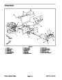
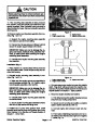
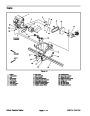


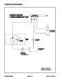

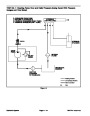


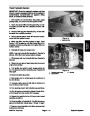

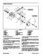


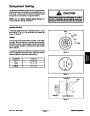
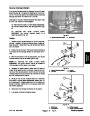


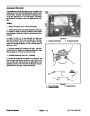


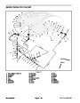
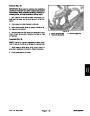
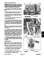
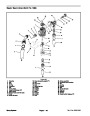


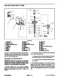


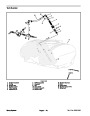
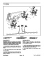
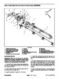
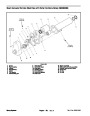


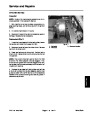
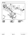
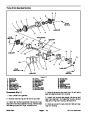

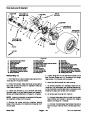

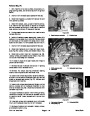
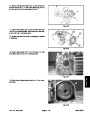
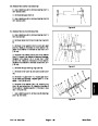
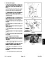
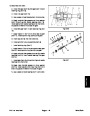


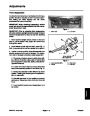


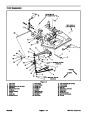


Removal and Inspection (Fig. 23)
3
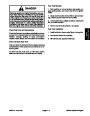
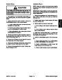
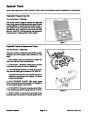
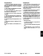
IMPORTANT: Make sure to remove and neutralize
chemicals from spray components before disas-
sembly. Wear protective clothing, chemical resist-
ant gloves, and eye protection during repair.
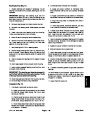
1.
gage parking brake, and remove key from the ignition
switch.
Park machine on a level surface, stop engine, en-
1
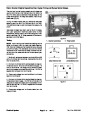
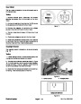
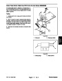
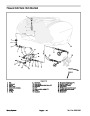
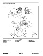
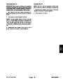
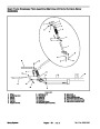
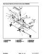
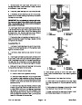
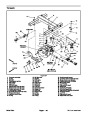
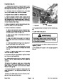
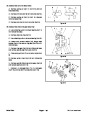
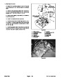
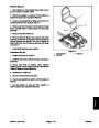
2.
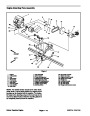
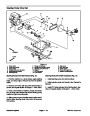
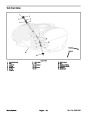
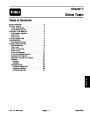
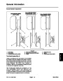
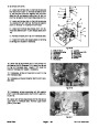
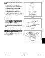
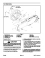
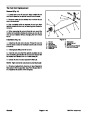
Remove master boom valve handle, spray control
panel, and spray console from machine (Fig. 24).
2
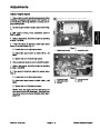
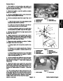
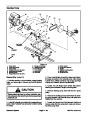
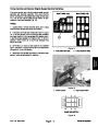
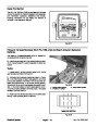
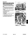
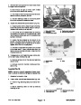
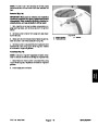
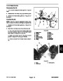
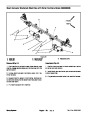
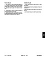
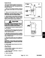
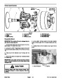
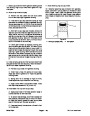
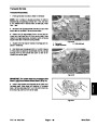
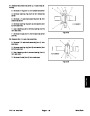
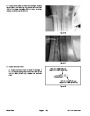
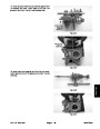
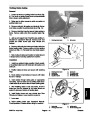
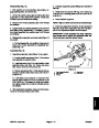
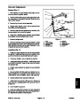
3.
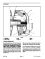
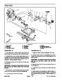
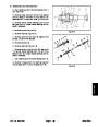
Loosen and remove nut that secures flow sensor to
housing (Fig. 25). Carefully remove flow sensor from
flowmeter housing.
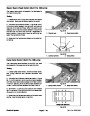
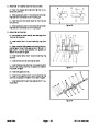
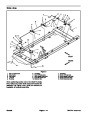
Figure 24
1.
2.
Boom valve handle
Spray console panel
3.
Spray console
4.
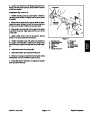
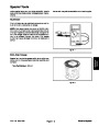
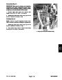
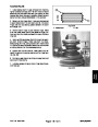
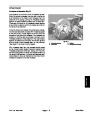
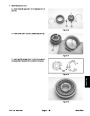
Clean rotor, rotor shaft, and flowmeter sensor if re-
quired (see Operator’s Manual).
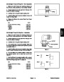
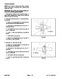
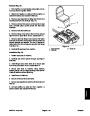
5.
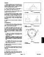
With the flow sensor harness connected to the ma-
chine and the ignition key in the ON position, slowly spin
the flowmeter rotor. The LED on the flowmeter should il-
luminate as a rotor magnet passes the flow sensor and
should go out as the next rotor magnet passes the sen-
sor.
NOTE: When using a magnet to check the flowmeter,
make sure to alternately use both north and south poles
of the magnet.
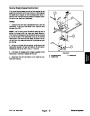
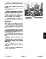
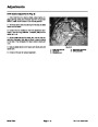
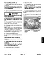
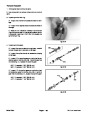
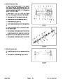
6.
If the flowmeter LED does not flash, remove rotor
2
and rotor shaft from sensor. With the flowmeter harness
connected to the machine and the ignition key in the ON
position, slowly pass alternate poles of a magnet past
the flow sensor. If the flowmeter LED flashes as the
magnet poles pass the sensor, replace the rotor and ro-
tor shaft. If the flowmeter LED does not flash as the mag-
net poles pass the sensor, replace the flow sensor.
1
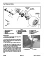
Figure 25
1.
Flowmeter
3
2.
Hose to boom valves
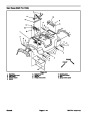
7.
If necessary, remove flowmeter housing using Fig-
ures 23 and 25 as guides (also see Spray Control (Multi
Pro 1200) in this section). Discard all removed o–rings
and gaskets.
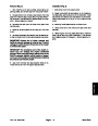
Assembly (Fig. 23)
1
NOTE: Coat all o–rings with vegetable oil before instal-
lation to reduce the chance of damage during assembly.
2
3
NOTE: When installing flow sensor into housing, make
sure to align locating pin on sensor with hole in housing.
1.
Reassemble flowmeter using Figures 23 and 25 as
guides. Replace all removed o–rings and gaskets.
2.
3.
Operate spray system and check for leaks.
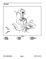
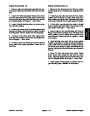
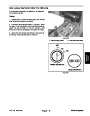
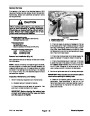
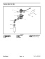
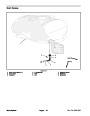
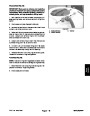
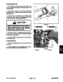
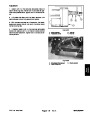
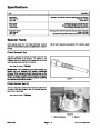
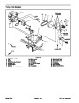
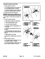
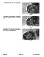
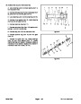
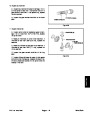
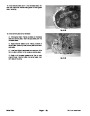
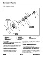
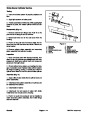
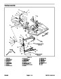
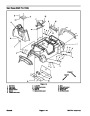
Figure 26
3.
1.
2.
Rotor shaft
Rotor
Rotor magnet
Install spray console, spray control panel, and mas-
ter boom valve handle to machine (Fig. 24).
Multi Pro 1200/1250
Spray System
Page 6 – 27
| Categories | Lawn Mower Manual, Sprinkler and Irrigation Manuals, Toro Sprinkler and Irrigation Manuals |
|---|---|
| Tags | Toro Multi Pro 1200, Toro Multi Pro 1250 |
| Download File |
|
| Document Type | Service Manual |
| Language | English |
| Product Brand | Toro. Customer Service Representatives are available by phone:
Monday - Friday 7:30 a.m. to 9:00 p.m. (CDT) - Saturday 8:00 a.m. to 8:00 p.m. (CDT) - Sunday 10:00 a.m. to 8:00 p.m. (CDT)
Canada 1-888-225-4886 USA 1-888-384-9939, Lawn Mower |
| Document File Type | |
| Publisher | toro.com |
| Wikipedia's Page | Toro Company |
| Copyright | Attribution Non-commercial |
(0 votes, average: 0 out of 5)