


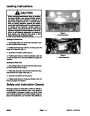


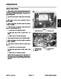
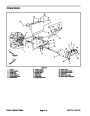
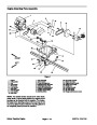
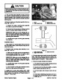
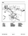


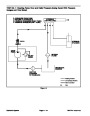


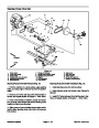

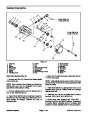
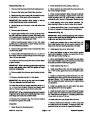


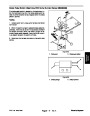


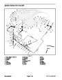
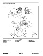
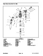


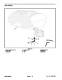
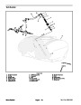
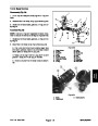
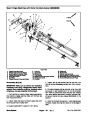
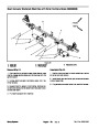

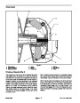


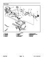
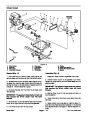
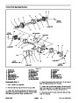


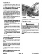
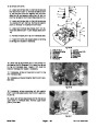
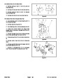
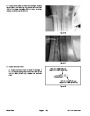
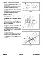


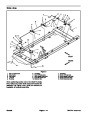
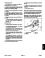


Disassembly (Fig. 13)
3. Lubricate suspension grease fittings (see Operator’s
Manual).
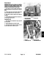
1.
Park machine on a level surface, stop engine, en-
gage parking brake, and remove key.
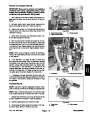
4. Install wheel and secure with lug nuts. Torque lug
nuts evenly in a crossing pattern from 55 to 65 ft–lb (75
to 88 N–m).
2.
Lift front of machine using a jack or hoist to allow front
suspension to hang freely from machine. Chock rear
wheels to prevent vehicle from shifting.
5. Lower machine to ground.
3.
Remove front wheel assembly (see Front Wheels
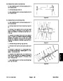
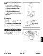
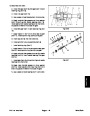
NOTE: Right and left tie rods should be identical length.
and Brakes).
6.
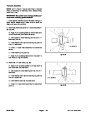
Check and adjust front wheel toe–in (see Operator’s
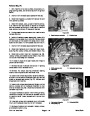
4.
Support brake and spindle assembly to prevent them
Manual). Check front suspension (see Front Suspen-
sion in the Adjustments section of this Chapter).
from falling during disassembly. If necessary, remove
front brake assembly from spindle (see Front Wheels
and Brakes).
IMPORTANT: If axle assembly has been replaced,
front wheel toe–in should be rechecked after ma-
chine has been used for several hours.
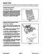
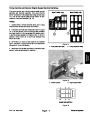
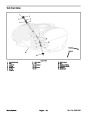
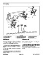
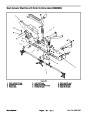
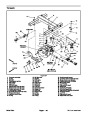
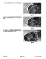
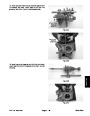
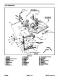
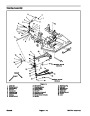
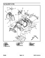
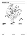
5.
Disassemble suspension as needed using Figure 13
as a guide.
2
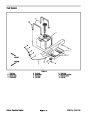
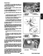
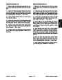
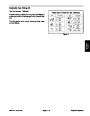
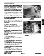
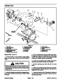
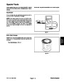
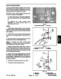
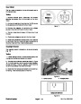
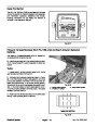
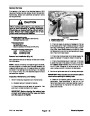
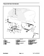
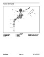
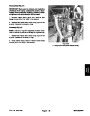
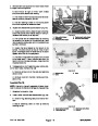
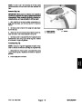
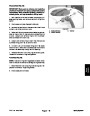
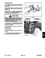
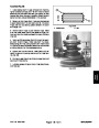
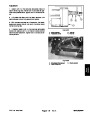
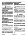
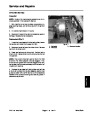
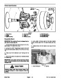
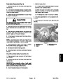
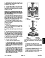
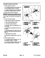
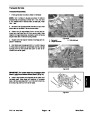
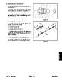
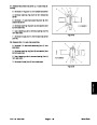
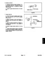
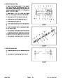
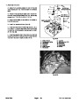
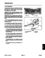
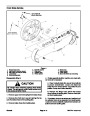
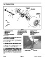
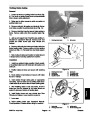
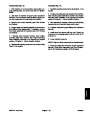
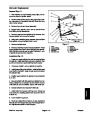
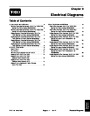
A. During disassembly, note position of cap screw in
torque arm of axle assembly for reassembly pur-
poses (Fig. 14).
3
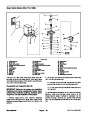
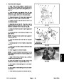
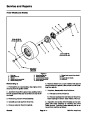
Assembly (Fig. 13)
1
1.
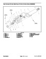
Assemble suspension using Figure 13 as a guide.
A. Loosely install cap screws (Item 1) that secure
axle assembly to machine frame.
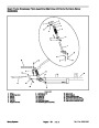
B. Install cap screw (Item 2) in noted location of axle
assembly torque arm (Fig. 14). Torque cap screw
from 130 to 150 ft–lb (176 to 203 N–m).
4
5
2
NOTE LOCATION
Figure 14
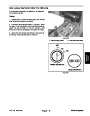
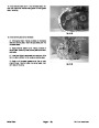
C. Torque cap screws (Item 1) that secure axle as-
sembly to machine frame from 200 to 250 ft–lb (271
to 339 N–m).
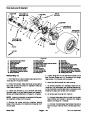
1.
2.
3.
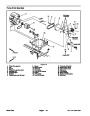
Axle assembly (RH)
Cap screw
Frame
4.
5.
Cap screw
Lock nut
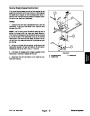
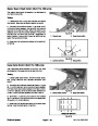
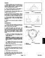
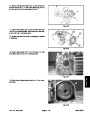
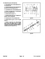
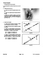
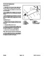
D. If ball joints were loosened or removed from
spindle, tighten slotted hex nut to a minimum of 140
ft–lb (189 N–m). If necessary for cotter pin installa-
tion, tighten slotted hex nut further until cotter pin can
be installed.
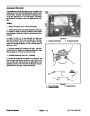
2.
After assembly is complete, make sure that compo-
nents do not contact hoses and/or wires.
Multi Pro 1200/1250
Page 8 – 17
Chassis
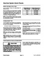
| Categories | Lawn Mower Manual, Sprinkler and Irrigation Manuals, Toro Sprinkler and Irrigation Manuals |
|---|---|
| Tags | Toro Multi Pro 1200, Toro Multi Pro 1250 |
| Download File |
|
| Document Type | Service Manual |
| Language | English |
| Product Brand | Toro. Customer Service Representatives are available by phone:
Monday - Friday 7:30 a.m. to 9:00 p.m. (CDT) - Saturday 8:00 a.m. to 8:00 p.m. (CDT) - Sunday 10:00 a.m. to 8:00 p.m. (CDT)
Canada 1-888-225-4886 USA 1-888-384-9939, Lawn Mower |
| Document File Type | |
| Publisher | toro.com |
| Wikipedia's Page | Toro Company |
| Copyright | Attribution Non-commercial |
(0 votes, average: 0 out of 5)