


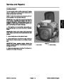
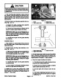


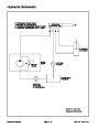

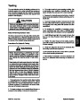


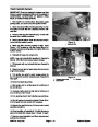

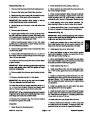


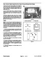
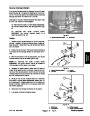


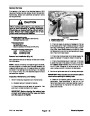


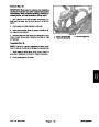
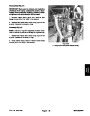


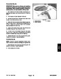
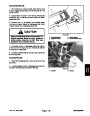
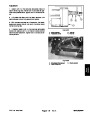


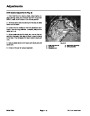
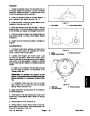
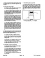


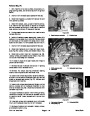


CAUTION
1
Rotate steering wheel to relieve hydraulic sys-
tem pressure and avoid injury from pressurized
hydraulic oil.
3
2
4
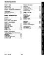
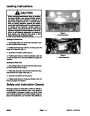
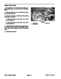
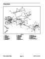
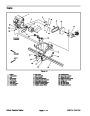
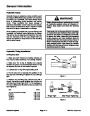
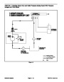
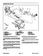
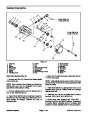
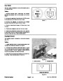
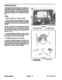
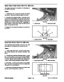
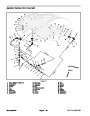
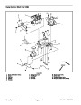
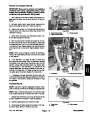
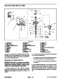
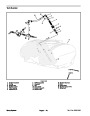
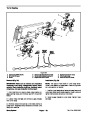
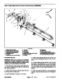
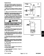
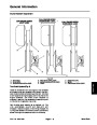
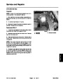
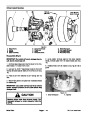
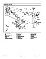
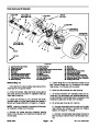
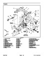
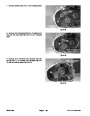
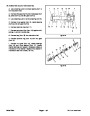
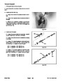
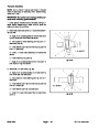
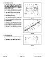
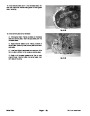
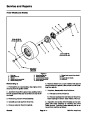
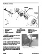
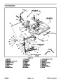
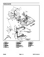
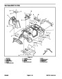
11.
If the mounting plate assembly is being removed
from machine, label all hydraulic connections for reas-
sembly purposes. Clean hydraulic hose ends prior to
disconnecting the hoses. Remove hydraulic hoses from
steering pump.
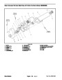
Figure 11
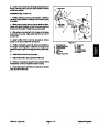
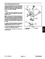
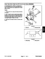
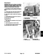
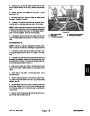
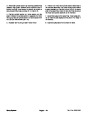
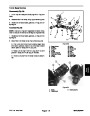
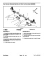
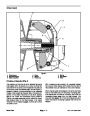
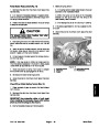
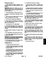
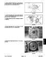
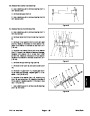
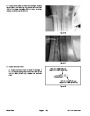
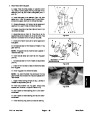
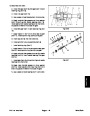
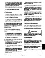
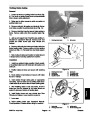
12.Remove
chine (Fig. 7 and 11):
engine mounting plate assembly from ma-
1.
2.
Frame
3.
4.
Engine mount
Negative battery cable
Engine support strap
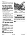
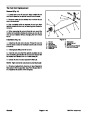
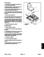
A. Support the engine mounting plate assembly
from below to prevent it from falling.
B. Remove four (4) cap screws and flange nuts that
secure the engine support straps to the frame.
2
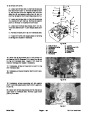
IMPORTANT: Make sure not to damage the en-
gine, fuel hoses, hydraulic lines, electrical har-
ness, or other parts while lowering the engine
mounting plate assembly.
3
1
C. Carefully lower engine mounting plate assembly
from machine.
Installation (Fig. 7)
1.
Place machine on a level surface with key removed
from the ignition switch. Chock wheels to keep the ma-
chine from moving.
2
2.
Reinstall engine mounting plate assembly to ma-
chine (Fig. 7 and 11):
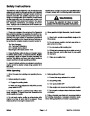
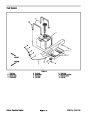
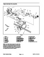
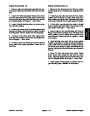
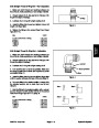
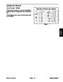
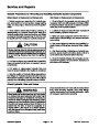
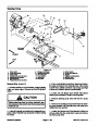
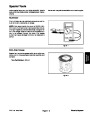
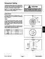
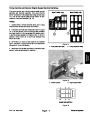
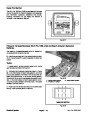
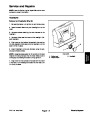
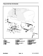
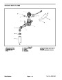
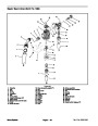
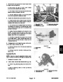
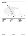
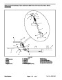
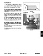
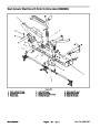
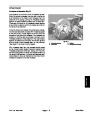
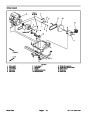
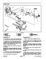
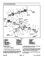
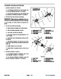
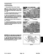
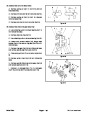
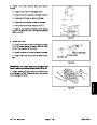
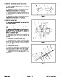
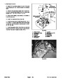
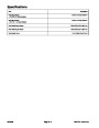
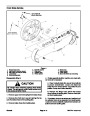
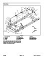
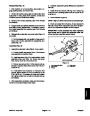
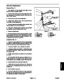
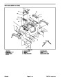
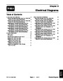
Figure 12
1.
2.
Engine support strap
3.
Engine mount tube
A. Make sure that engine mounts are assembled to
mounting straps correctly (Fig. 12). Position engine
mounting plate assembly under machine.
Engine mount cushion
4.
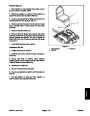
Connect spray pump coupler to pump drive electric
clutch. Plug clutch wiring connector into machine har-
ness (see Pump Drive Electric Clutch in the Service and
Repairs Section of Chapter 6 – Spray System).
IMPORTANT: Make sure not to damage the en-
gine, fuel hoses, hydraulic lines, electrical har-
ness, or other parts while raising the engine
mounting plate assembly.
5.
Reconnect engine electrical connections.
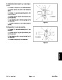
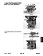
B. Carefully raise engine mounting plate assembly
to machine frame.
A. Pull wiring harness into position keeping harness
away from any moving components.
C. Secure engine mounting plate assembly to frame
with four (4) cap screws and flange nuts.
B. Secure two (2) red wires and positive (+) battery
cable to starter solenoid stud with nut.
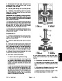
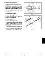
3.
Position key in pump drive gearbox shaft. Install
C. Connect engine wire harness to main wire har-
ness.
transaxle drive shaft to pump drive gearbox (see Pump
Drive Gearbox in the Service and Repairs Section of
Chapter 7 – Drive Train).
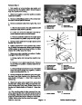
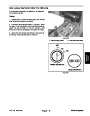
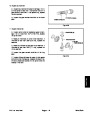
D. From below, install flange head screw and nut un-
der starter motor that secures engine and negative
(–)
cable (Fig. 11).
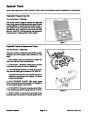
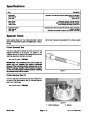
Kohler Gasoline Engine
Multi Pro 1200/1250
Page 3 – 12
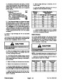
| Categories | Lawn Mower Manual, Sprinkler and Irrigation Manuals, Toro Sprinkler and Irrigation Manuals |
|---|---|
| Tags | Toro Multi Pro 1200, Toro Multi Pro 1250 |
| Download File |
|
| Document Type | Service Manual |
| Language | English |
| Product Brand | Toro. Customer Service Representatives are available by phone:
Monday - Friday 7:30 a.m. to 9:00 p.m. (CDT) - Saturday 8:00 a.m. to 8:00 p.m. (CDT) - Sunday 10:00 a.m. to 8:00 p.m. (CDT)
Canada 1-888-225-4886 USA 1-888-384-9939, Lawn Mower |
| Document File Type | |
| Publisher | toro.com |
| Wikipedia's Page | Toro Company |
| Copyright | Attribution Non-commercial |
(0 votes, average: 0 out of 5)