

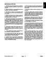


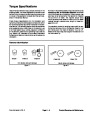
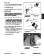


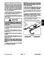


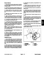


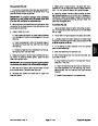


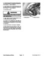


Procedure for Cutting Deck Manifold Relief
Pressure Test
11.If specification is not met, adjust or clean relief valve
in deck manifold port (RV1). Adjust relief valve as fol-
lows:
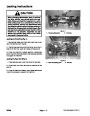
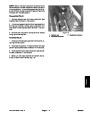
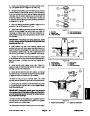
1.
Make sure hydraulic oil is at normal operating tem-
perature by operating the machine for approximately 10
minutes. Make sure the hydraulic tank is full.
NOTE: Do not remove valve from the hydraulic
manifold for adjustment.
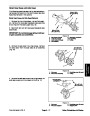
2.
lowered and off. Make sure engine is off and the parking
brake is engaged.
Parkmachineonalevelsurfacewiththecuttingdeck
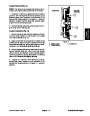
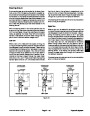
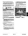
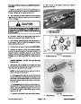
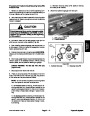
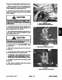
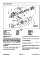
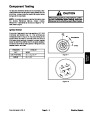
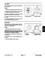
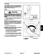
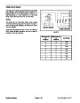
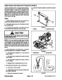
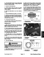
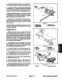
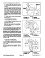
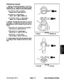
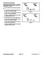
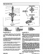
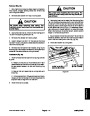
A. Remove cap on relief valve with an allen wrench.
B. To increase pressure setting, turn the adjust-
ment screw on the valve in a clockwise direction. A
1/8
in relief pressure.
turnonthescrewwillmakeameasurablechange
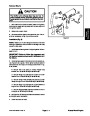
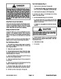
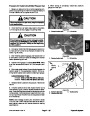
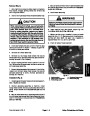
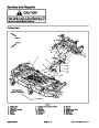
CAUTION
C. To decrease pressure setting, turn the adjust-
mentscrew onthevalve inacounterclockwise direc-
tion. A 1/8 turn on the screw will make a measurable
change in relief pressure.
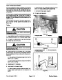
Prevent personal injury and/or damage to equip-
ment. Read all WARNINGS, CAUTIONS and Pre-
cautions for Hydraulic Testing at the beginning
of this section.
D. Install and tighten cap to secure adjustment. Re-
check relief pressure and readjust as needed.
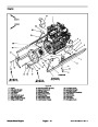
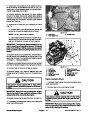
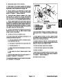
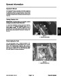
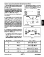
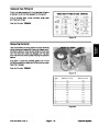
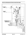
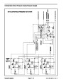
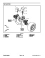
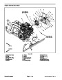
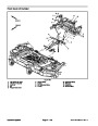
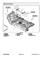
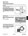
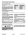
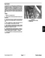
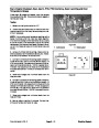
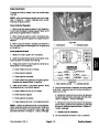
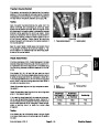
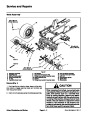
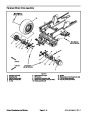
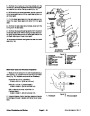
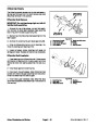
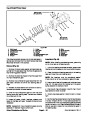
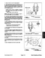
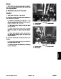
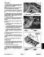
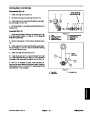
3.
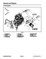
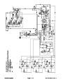
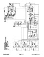
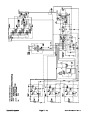
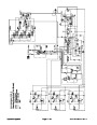
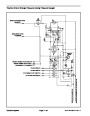
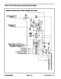
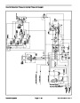
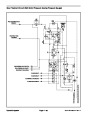
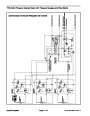
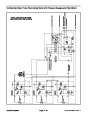
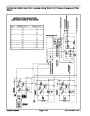
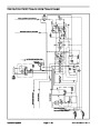
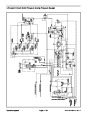
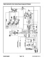
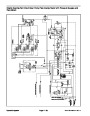
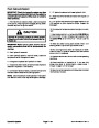
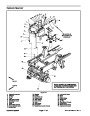
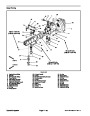
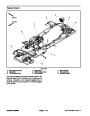
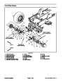
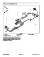
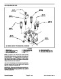
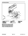
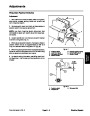
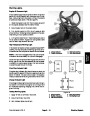
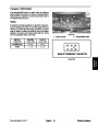
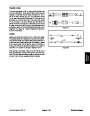
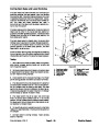
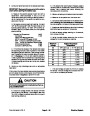
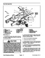
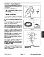
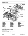
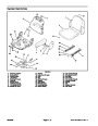
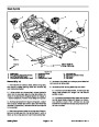
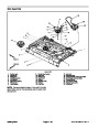
Locate deck manifold to be tested (Fig. 34). Discon-
nect hydraulic hose at deck manifold port (M1).
12.Disconnect
tester from manifold and hose. Recon-
nect hydraulic hose that was disconnected for test pro-
cedure.
NOTE: Analternativetousingmanifoldport(M1)would
be to disconnect the inlet hydraulic hose at deck motor.
4.
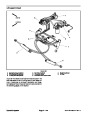
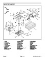
Install tester with pressure gauges and flow meter in
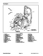
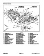
TO OIL COOLER
3
series with the the disconnected hose and hydraulic
manifold port (M1) (or motor inlet if hose was discon-
nected at deck motor).
1
RIGHT
FRONT
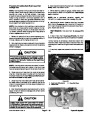
5.
Make sure the flow control valve on tester is fully
open.
6.
speed. Check for hydraulic leakage and correct before
proceeding with test.
After installing tester, start engine and run at idle
2
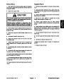
CAUTION
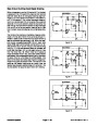
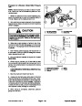
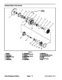
Figure 34
Keep away from deck during test to prevent per-
sonal injury from the cutting blades.
1.
2.
Center deck manifold
LH wing deck manifold
3. RH wing deck manifold
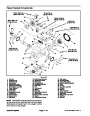
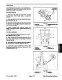
7.
the cutting deck.
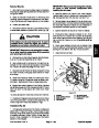
Operate engine at full speed (2870 RPM). Engage
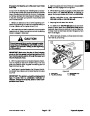
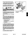
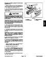
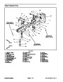
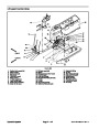
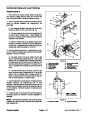
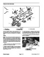
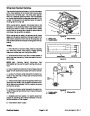
FRONT DECK MANIFOLD SHOWN
2
1
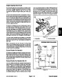
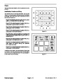
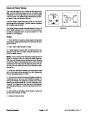
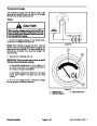
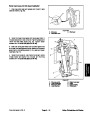
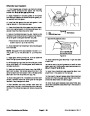
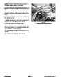
8.
Watch pressure gauge carefully while slowly closing
the flow control valve to fully closed.
9.
As the relief valve lifts, system pressure should be
approximately:
3
2900
to 3100 PSI (200 to 213 bar) for the center
deck and LH wing deck
1900
to 2100 PSI (131 to 144 bar) for the RH wing
deck
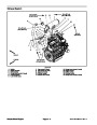
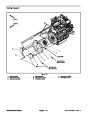
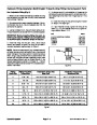
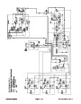
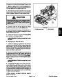
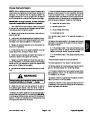
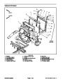
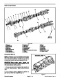
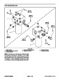
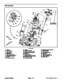
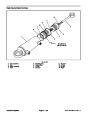
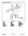
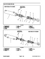
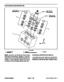
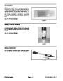
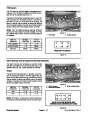
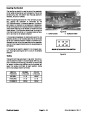
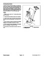
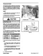
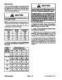
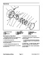
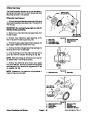
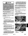
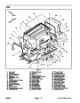
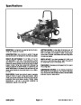
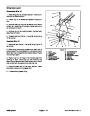
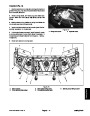
Figure 35
3. Relief valve cap
1.
2.
Deck manifold
Relief valve
10.Disengage
test results.
cutting deck. Shut off engine and record
Groundsmaster 4100--D
Page 4 -- 45
Hydraulic System
| Categories | Lawn Mower Manual, Sprinkler and Irrigation Manuals, Toro Sprinkler and Irrigation Manuals |
|---|---|
| Tags | Toro Groundsmaster 30413, Toro Groundsmaster Groundsmaster 4100 D |
| Download File |
|
| Document Type | Service Manual |
| Language | English |
| Product Brand | Toro. Customer Service Representatives are available by phone:
Monday - Friday 7:30 a.m. to 9:00 p.m. (CDT) - Saturday 8:00 a.m. to 8:00 p.m. (CDT) - Sunday 10:00 a.m. to 8:00 p.m. (CDT)
Canada 1-888-225-4886 USA 1-888-384-9939, Lawn Mower |
| Document File Type | |
| Publisher | toro.com |
| Wikipedia's Page | Toro Company |
| Copyright | Attribution Non-commercial |
(0 votes, average: 0 out of 5)
At only 700mm wide the Mini Dumper is even at home on tight access
sites. No need to grunt, groan, and force the
mower about the yard. The US will be getting a revised 2011 Jeep Wrangler but the diesel option will not be offered in the United States.