


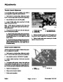

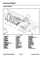
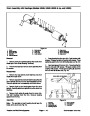
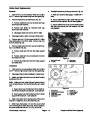
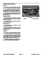


Brake Band Replacement
Removal
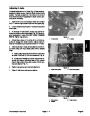
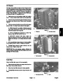
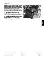
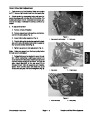
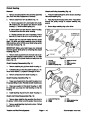
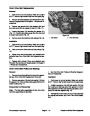
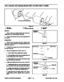
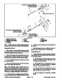
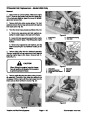
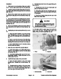
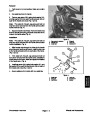
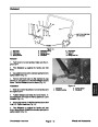
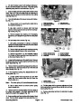
6. Reinstall interference previously removed (Fig. 34).
1.
is OFF. Remove high tension lead from the spark plug.
Park mower on a level surface. Make sure engine
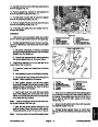
A. Make sure clutch is disengaged. Install both V–
belts.
2.
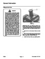
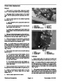
Remove interference to brake band (Fig. 34).
B. Secure belt shield to engine block with both cap
screws and lock washers. Do not over tighten.
A. Remove bellcrank cover by removing both cap
screws and lock washers.
C. Secure bellcrank cover to counter shaft housing
with both cap screws and lock washers. Do not
over tighten.
B. Remove belt shield by removing both cap
screws and lock washers.
C. Disengage clutch and remove both V–belts.
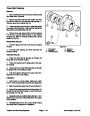
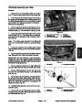
Disengage brake to allow removal of brake band.
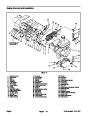
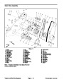
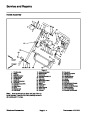
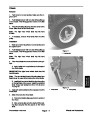
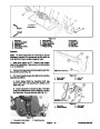
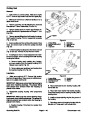
Remove lock nut (17) from power shaft (57). Slide
3
3.
4.
4
input shaft pulley (16) off the shaft. Remove key (18)
from the shaft (Fig. 33).
3
2
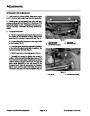
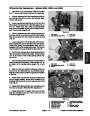
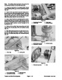
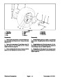
5.
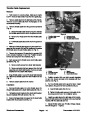
Remove brake band (25) from counter shaft hous-
ing (1) as follows (Fig. 33).
A. Remove cotter pin (23) from the brake support
(21).
1
B. Remove cotter pin (24) and clevis pin (20) from
the brake lever (19).
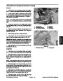
Figure 34
1.
2.
Bell crank cover
V–belts
3.
4.
Cap screw
Belt shield
C. Remove the brake band from the brake support
and brake lever.
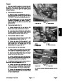
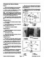
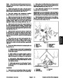
Installation
1
2
3
7
9
1.
Park mower on a level surface. Make sure engine
is OFF. Remove high tension lead from the spark plug.
2.
3.
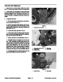
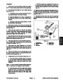
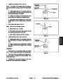
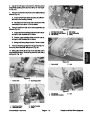
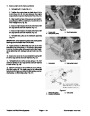
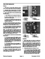
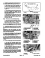
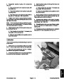
Disengage brake to allow installation of brake band.
Attach new brake band to the counter shaft housing
as follows (Fig. 35).
8
Note:
Make sure both cotter pins are locked so there
5
is no contact between the input shaft pulley and cotter
pins.
6
4
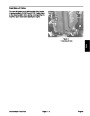
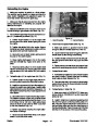
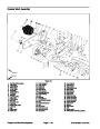
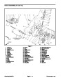
Figure 35
A. Secure lower eye of brake band to the brake le-
ver with the clevis pin and cotter pin. Lock cotter pin.
1.
2.
3.
4.
5.
Brake band
6.
Clevis pin
Counter shaft housing
Cotter pin
7.
8.
9.
Brake support
Power shaft
Lock nut
B. Secure upper eye of the brake band to the brake
support with cotter pin. Lock cotter pin.
Input shaft pulley
Brake lever
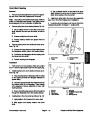
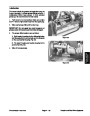
4.
Apply never seize to the keyway area of the power
shaft (57). Install key (18) to the shaft (Fig. 33).
5.
(57)
Slide input shaft pulley (16) onto the power shaft
and through the brake band (25). Secure pulley to
the power shaft with lock nut (17) (Fig. 33 and 35).
Greensmaster 1000/1600
Page 4 – 21
Traction and Reel Drive Systems
| Categories | Lawn Mower Manual, Sprinkler and Irrigation Manuals, Toro Sprinkler and Irrigation Manuals |
|---|---|
| Tags | Toro Greensmaster 1000, Toro Greensmaster 1600, Toro Greensmaster 96889SL |
| Download File |
|
| Document Type | Catalog |
| Language | English |
| Product Brand | Toro. Customer Service Representatives are available by phone:
Monday - Friday 7:30 a.m. to 9:00 p.m. (CDT) - Saturday 8:00 a.m. to 8:00 p.m. (CDT) - Sunday 10:00 a.m. to 8:00 p.m. (CDT)
Canada 1-888-225-4886 USA 1-888-384-9939, Lawn Mower |
| Document File Type | |
| Publisher | toro.com |
| Wikipedia's Page | Toro Company |
| Copyright | Attribution Non-commercial |
(0 votes, average: 0 out of 5)