


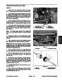
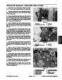


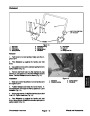


Brake Cable Replacement
Removal
6
2
5
1.
Park mower on a level surface. Make sure engine
7
is OFF. Remove high tension lead from the spark plug.
2.
Disengage brake to release tension on the brake
3
cable.Removecabletiesfromtheleftsideofthehandle.
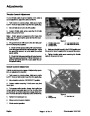
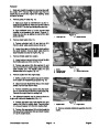
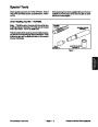
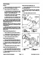
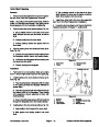
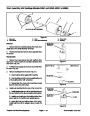
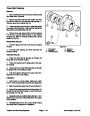
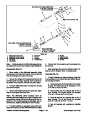
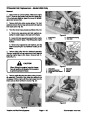
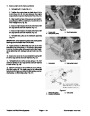
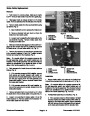
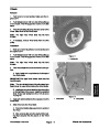
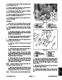
3.
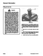
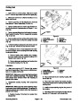
as follows (Fig. 5):
Remove brake cable from the countershaft housing
1
4
A. Open bellcrank cover to access the brake lever.
B. Remove shoulder bolt and lock nut from the
brake lever and cable eyelet.
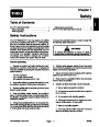
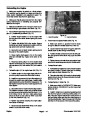
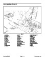
Figure 5
1.
2.
3.
4.
Brake lever
Shoulder bolt
Lock nut
5.
6.
7.
Rear nut
Brake cable
Countershaft housing
C. Loosen rear nut attaching the brake cable to the
countershaft housing. Remove brake cable from
housing and brake lever
Cable eyelet
7
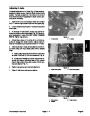
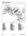
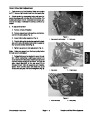
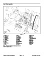
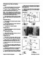
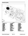
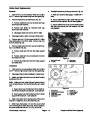
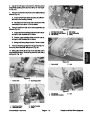
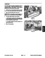
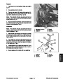
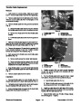
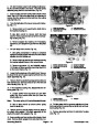
4.
Make sure brake is disengaged and the clutch is en-
gaged so the console (29) can be positioned to access
the brake lever (18) and brake cable (15) (Fig. 2).
5
6
3
5.
Remove four screws (13) securing the console (29)
to the console brackets (10 and 19). Position console
forward and away from the brackets (Fig. 2).
4
Note:
On models without the operator presence kit,
8
the bail assembly, switch, and switch bracket are not
installed on the handle assembly. The shoulder bolt and
spacer are substituted by an additional screw on both
sides of the handle assembly (Fig. 2 and 6).
1
2
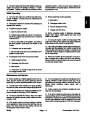
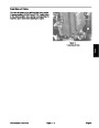
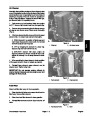
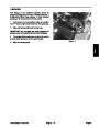
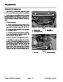
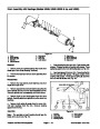
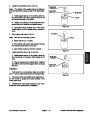
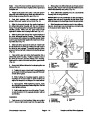
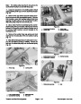
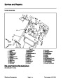
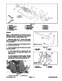
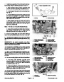
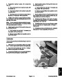
Figure 6
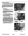
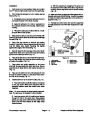
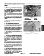
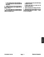
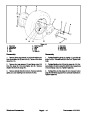
6.
follows (Fig. 6):
Gain access to the brake lever and brake cable as
1.
2.
3.
4.
Screw
Switch bracket
Switch
5.
6.
7.
8.
Shoulder bolt
Spacer
Bail assembly
Brake skid bracket
Console bracket
A. If the operator presence kit is installed, remove
both screws and switch bracket (with switch at-
tached) from the brake skid bracket. Remove shoul-
der bolt and spacer from the bail assembly and
brake skid bracket. Remove console bracket from
the brake skid bracket.
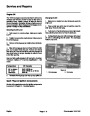
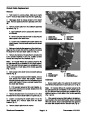
Installation
1.
Secure brake cable (15) eyelet to the brake lever
with the shoulder bolt (14) and lock nut (11) (Fig. 2).
(18)
Note:
On models without the operator presence kit,
B. If the operator presence kit is not installed, re-
move three screws and console bracket from the
brake skid bracket.
the bail assembly, switch, and switch bracket are not
installed on the handle assembly. The shoulder bolt and
spacer are substituted by an additional screw on both
sides of the handle assembly (Fig. 2 and 6).
7.
Remove shoulder bolt (14) and lock nut (11) from
the brake lever (18) and brake cable (15) eyelet (Fig. 2).
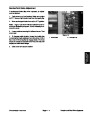
2.
Reinstall bail assembly and brackets. (Fig. 6).
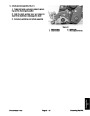
8.
brake bracket (17). Remove cable from the bracket. Re-
move brake cable from the mower.
Loosen nut securing the brake cable (15) to the
A. If the operator presence kit is installed, reinstall
console bracket and switch bracket (with switch at-
tached) to the brake skid bracket. Secure brackets
with both screws. Secure bail assembly and spacer,
to the brake skid bracket with the shoulder bolt.
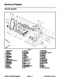
Wheels and Accessories
Greensmaster 1000/1600
Page 6 – 6
| Categories | Lawn Mower Manual, Sprinkler and Irrigation Manuals, Toro Sprinkler and Irrigation Manuals |
|---|---|
| Tags | Toro Greensmaster 1000, Toro Greensmaster 1600, Toro Greensmaster 96889SL |
| Download File |
|
| Document Type | Catalog |
| Language | English |
| Product Brand | Toro. Customer Service Representatives are available by phone:
Monday - Friday 7:30 a.m. to 9:00 p.m. (CDT) - Saturday 8:00 a.m. to 8:00 p.m. (CDT) - Sunday 10:00 a.m. to 8:00 p.m. (CDT)
Canada 1-888-225-4886 USA 1-888-384-9939, Lawn Mower |
| Document File Type | |
| Publisher | toro.com |
| Wikipedia's Page | Toro Company |
| Copyright | Attribution Non-commercial |
(0 votes, average: 0 out of 5)