


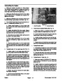

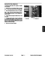
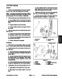


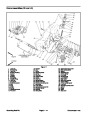


Installation
9. Reinstall belts to both drum drive assemblies as fol-
lows (Fig. 55):
1.
Park mower on a level surface. Make sure engine
is OFF. Remove high tension lead from the spark plug.
A. Reinstall belt onto the drum shaft pulley and
pulley on both sides of mower.
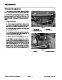
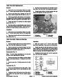
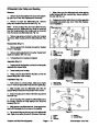
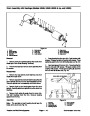
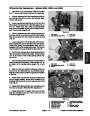
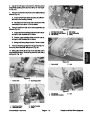
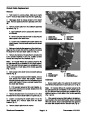
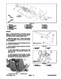
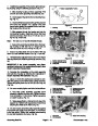
2.
Install new belt to the differential pulley and counter-
shaft pulley. Slide differential assembly to the right side
plate (Fig. 62).
B. Swing idler pulley into belt. Reinstall upper car-
riage bolts and lock nuts to both sides of the frame.
Do not tighten.
3.
Secure three socket head cap screws and lock
washerstothesideplate(RH)andbearinghousing(Fig.
61).
C. Keep lower carriage bolts and lock nuts on both
sides of the frame loose.
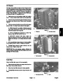
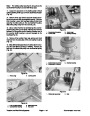
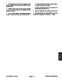
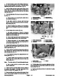
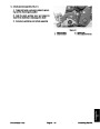
4.
Use a rubber hammer to carefully tap the counter-
shaft housing onto the power shaft. Alternate the ham-
mer between the long axle and the bearing housing end
of the counter shaft housing to prevent damage to the
bearings (Fig. 60).
CAUTION
When lifting the engine to the frame, have
at least two (2) people lift the engine to
prevent personal injury.
5.
Secure countershaft housing to the frame with the
four cap screws, lock washers, and flat washers (Fig.
50).
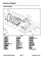
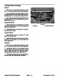
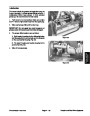
10.
mower onto the frame. Reinstall cable clips to the
cables, wires, and handle assembly (Fig. 52)
Lift engine with the engine base from behind the
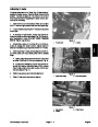
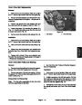
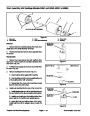
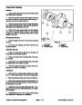
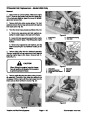
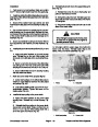
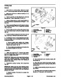
6.
54).
Install pulley to the short axle as follows (Fig. 57 and
A. Apply anti–seize lubricant to the axle keyway
area. Reinstall key to the axle. Slide pulley onto
short axle on the right side of the countershaft hous-
ing.
3
3
B. Screw nut onto the short axle of the differential.
Use drift punch in the hole of the short axle while
torquing the nut from 30 to 40 ft–lb (4.1 to 5.5 kg–m).
C. Secure differential boot to the bearing housing
with the small hose clamp.
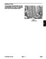
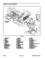
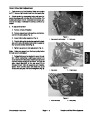
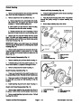
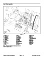
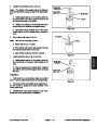
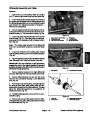
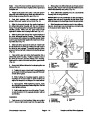
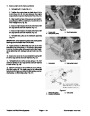
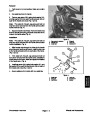
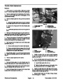
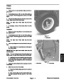
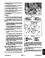
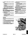
7.
Make sure drum belts will be properly aligned.
A. Center both pulleys on the differential axles to
obtain an equal distance between the side plates
and pulleys (Fig. 63).
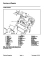
Figure 63
1.
Pulley
2.
Side plate
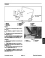
B. Lock collar by striking it with a punch in the coun-
terclockwise direction. Tighten set screw on the
locking collar (Fig. 58).
2
1
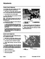
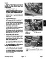
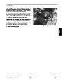
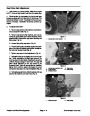
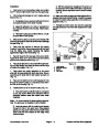
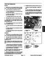
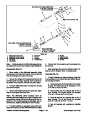
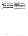
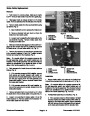
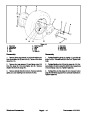
8.
Install shaft input pulley to the power shaft.
A. Apply anti–seize lubricant to the power shaft
keyway area. Reinstall key to shaft keyway (Fig.
56).
B. .Reinstall shaft input pulley to the power shaft.
Screw lock nut onto shaft. Torque nut from 30 to 40
ft–lb (4.1 to 5.5 kg–m) while locking shaft with a
9/16–inch
open end wrench (Fig. 64).
Figure 64
1.
Shaft input pulley
2.
Power shaft
Greensmaster 1000/1600
Page 4 – 33
Traction and Reel Drive Systems
| Categories | Lawn Mower Manual, Sprinkler and Irrigation Manuals, Toro Sprinkler and Irrigation Manuals |
|---|---|
| Tags | Toro Greensmaster 1000, Toro Greensmaster 1600, Toro Greensmaster 96889SL |
| Download File |
|
| Document Type | Catalog |
| Language | English |
| Product Brand | Toro. Customer Service Representatives are available by phone:
Monday - Friday 7:30 a.m. to 9:00 p.m. (CDT) - Saturday 8:00 a.m. to 8:00 p.m. (CDT) - Sunday 10:00 a.m. to 8:00 p.m. (CDT)
Canada 1-888-225-4886 USA 1-888-384-9939, Lawn Mower |
| Document File Type | |
| Publisher | toro.com |
| Wikipedia's Page | Toro Company |
| Copyright | Attribution Non-commercial |
(0 votes, average: 0 out of 5)