


Note:
placed, it is recommended to replace all four gears as a
complete set.
If any of the bevel or pinion gears need to be re-
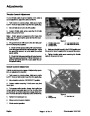
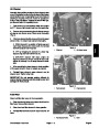
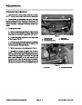
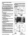
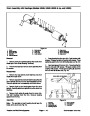
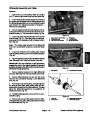
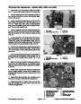
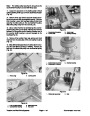
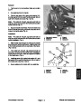
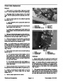
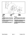
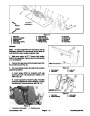
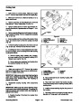
2. Slide pulley onto differential axle so threads extend
through pulley. Secure lock nuts and flat washers to the
differential assembly and pulley. (Fig. 42).
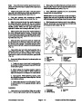
2.
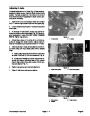
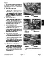
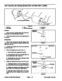
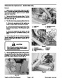
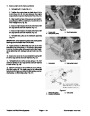
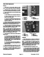
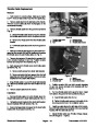
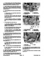
place with both retaining rings. Make sure flat side of re-
taining rings are away from the gear (Fig. 44).
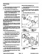
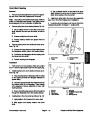
Attach bevel gears to the axles. Lock each gear in
3. Place differential assembly into the countershaft
housing with the long axle first.
IMPORTANT: For the remainder of this procedure,
support the axle so it is parallel to the drum. Pos-
sible damage to the bearings should be prevented.
3.
grease. Slide each washer onto an axle (Fig. 44).
Coat both washers with molybdenum disulfide
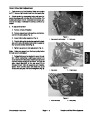
4.
Slide the long axle through the needle bearings of
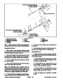
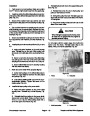
4. Slide flangettes and bearing onto the long differen-
tial axle. Secure jam nuts, lock washers, and cable clip
to the studs of screw plate (Fig. 40).
the differential carrier housing with the four threaded
holes. Thoroughly coat the bevel gear with molybdenum
disulfide grease. Make sure the gear back is flush
against the washer and housing inside face (Fig. 44).
5.
Slide the short axle through the needle bearings of
the other differential carrier housing. Thoroughly coat
the bevel gear with molybdenum disulfide grease. Make
sure the gear back is flush against the washer and hous-
ing inside face (Fig. 44).
4
3
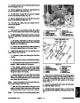
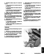
6.
Slide both pinion gears to the drive pin. Attach both
thrust washers to the drive pin. Make sure both ends of
the drive pin are exposed. Thoroughly coat the pinion
gears and drive shaft with molybdenum disulfide grease
(Fig. 44).
2
5
1
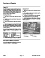
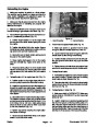
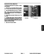
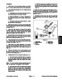
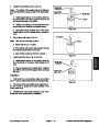
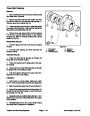
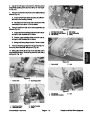
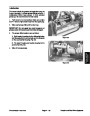
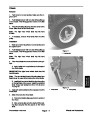
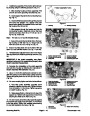
7.
Place pinion gear and drive shaft assembly into a
differential carrier housing. Position exposed ends of
the drive pin into the rounded insets of the housing.
Make sure the teeth of the bevel and pinion gears mesh
(Fig. 45).
6
7
8
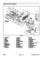
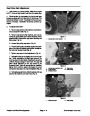
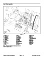
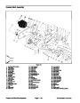
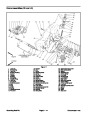
Figure 44
1.
2.
3.
4.
Bevel gear
Axle
5.
6.
7.
8.
Carrier housing
Pinion gear
Drive pin
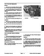
8.
Securebothdifferentialcarrierhousingstogetheras
Retaining ring
Washer
follows (Fig. 45):
Thrust washer
A. Position the open ends of each housing together
so the teeth of both bevel gears mess with the teeth
of both pinion gears.
2
3
B. While holding the housings together, twist the
housings so the four holes on each housing are
aligned to accept the the flanged hex head screws.
C. Insert screws. While tightening screws, make
sure that all the gears stay messed together. Do not
over tighten screws.
D. Hold housing and turn one of the axles. The oth-
er axle should turn in the opposite direction without
any binding.
1
4
2
ROUNDED INSET
Figure 45
Installation
1.
2.
3.
Pinion gear
Drive shaft
Carrier housing
4.
5.
Bevel gear
Axle
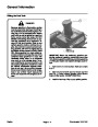
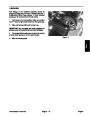
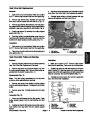
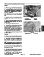
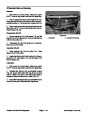
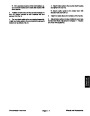
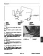
1.
is OFF. Remove high tension lead from the spark plug.
Park mower on a level surface. Make sure engine
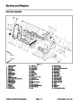
Greensmaster 1000/1600
Page 4 – 27
Traction and Reel Drive Systems
| Categories | Lawn Mower Manual, Sprinkler and Irrigation Manuals, Toro Sprinkler and Irrigation Manuals |
|---|---|
| Tags | Toro Greensmaster 1000, Toro Greensmaster 1600, Toro Greensmaster 96889SL |
| Download File |
|
| Document Type | Catalog |
| Language | English |
| Product Brand | Toro. Customer Service Representatives are available by phone:
Monday - Friday 7:30 a.m. to 9:00 p.m. (CDT) - Saturday 8:00 a.m. to 8:00 p.m. (CDT) - Sunday 10:00 a.m. to 8:00 p.m. (CDT)
Canada 1-888-225-4886 USA 1-888-384-9939, Lawn Mower |
| Document File Type | |
| Publisher | toro.com |
| Wikipedia's Page | Toro Company |
| Copyright | Attribution Non-commercial |
(0 votes, average: 0 out of 5)