


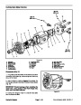

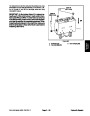


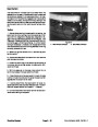


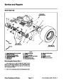

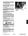


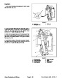

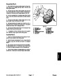


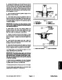
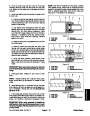


7.
Remove gear pump from machine (see Gear Pump
Removal in this section).
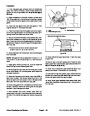
8.
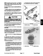
Support the piston pump to prevent it from falling
while removing two (2) cap screws and washers retain-
ing pump assembly to engine adapter plate. Carefully
pull pump assembly from adapter plate and raise it out
of the machine.
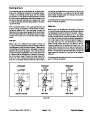
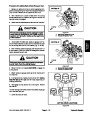
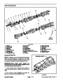
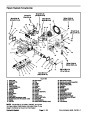
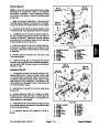
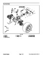
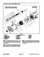
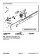
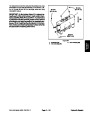
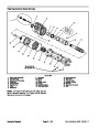
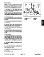
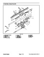
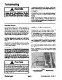
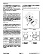
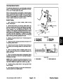
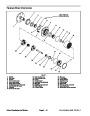
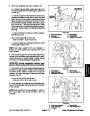
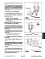
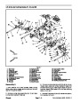
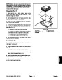
1
2
9.
pump, mark fitting orientation to allow correct assembly.
Remove fittings from pump and discard O--rings.
If hydraulic fittings are to be removed from piston
3
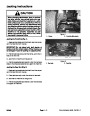
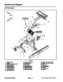
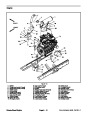
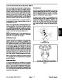
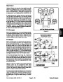
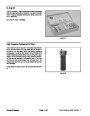
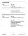
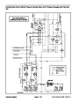
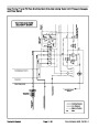
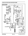
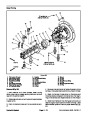
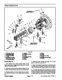
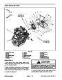
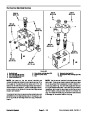
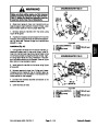
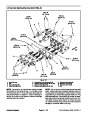
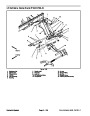
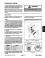
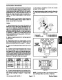
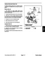
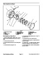
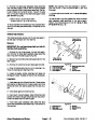
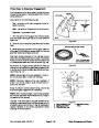
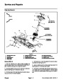
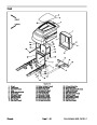
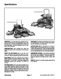
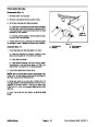
Installation (Fig. 60)
5
1.
If fittings were removed from piston pump, lubricate
4
and place new O--rings onto fittings. Install fittings into
pump ports using marks made during the removal pro-
cess to properly orientate fittings. Tighten fittings (see
Hydraulic Fitting Installation in the General Information
section of this chapter).
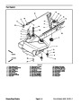
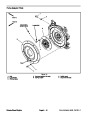
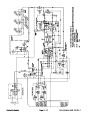
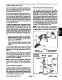
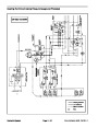
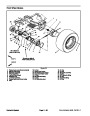
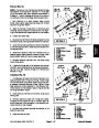
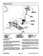
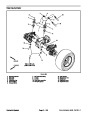
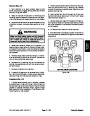
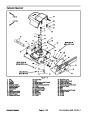
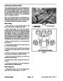
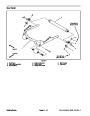
Figure 61
1.
2.
3.
Piston pump
4.
5.
Flange head screw
Lock nut
Neutral switch
Traction rod
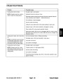
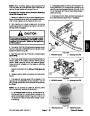
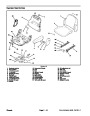
2.
Carefully lower piston pump into the machine and
position it to the engine adapter plate. Support pump to
prevent it from falling while installing two (2) cap screws
and washers securing piston pump to engine adapter
plate. Torque screws from 77 to 93 ft--lb (105 to 126
N--m).
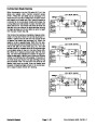
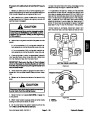
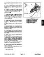
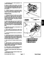
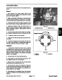
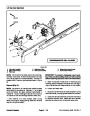
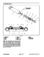
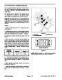
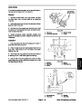
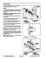
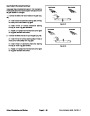
RIGHT
FRONT
3
4
3.
Install gear pump to piston pump (see Gear Pump
Installation in this section).
5
4.
and secure with flange head screw and lock nut (Fig.
61).
Position traction rod to control arm on piston pump
5.
traction pump.
Connect wire harness connector toneutral switch on
1
6
2
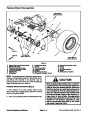
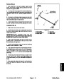
6.
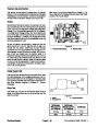
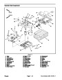
Remove plugs and caps from disconnected hydrau-
7
lic hoses and open ports of the pump assembly. Install
fittings and hoses to correct location on gear and piston
pumps (see Hydraulic Hose and Tube Installation in the
General Information section of this chapter).
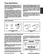
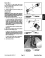
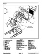
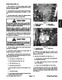
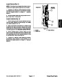
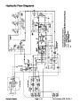
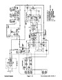
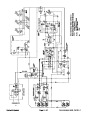
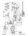
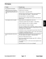
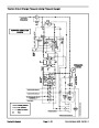
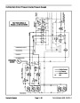
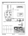
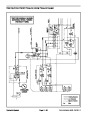
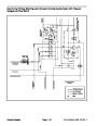
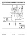
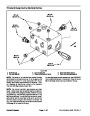
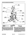
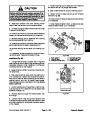
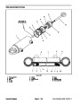
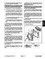
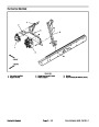
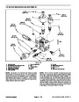
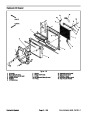
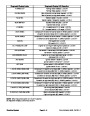
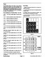
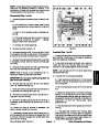
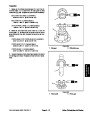
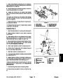
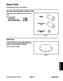
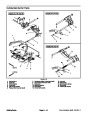
Figure 62
1.
2.
3.
4.
5.
6.
7.
Supply hose to deck manifold P1 port
Supply hose to deck manifold P2 port
Supply hose to fan manifold P2 port
Supply hose to fan manifold P1 port
Suction hose from filter manifold
Suction hose from reservoir
7.
rect oil.
Install new filter and fill hydraulic reservoir with cor-
Supply hose for charge circuit
8.
Disconnect engine run solenoid electrical connector
to prevent engine from starting. Prime pumps by turning
ignition key switch to crank engine for ten (10) seconds.
Repeat cranking procedure again.
9.
start the engine and check for proper operation.
Connect engine run solenoid electrical connector,
10.Properly
System).
fill hydraulic system (see Charge Hydraulic
11.
Stop engine and check for hydraulic oil leaks. Check
hydraulic reservoir oil level.
Groundsmaster 4500--D/4700--D
Page 4 -- 77
Hydraulic System
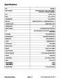
| Categories | Lawn Mower Manual, Sprinkler and Irrigation Manuals, Toro Sprinkler and Irrigation Manuals |
|---|---|
| Tags | Toro Groundsmaster 30857, Toro Groundsmaster 30858, Toro Groundsmaster 4500 D, Toro Groundsmaster 4700 D |
| Download File |
|
| Document Type | Service Manual |
| Language | English |
| Product Brand | Toro. Customer Service Representatives are available by phone:
Monday - Friday 7:30 a.m. to 9:00 p.m. (CDT) - Saturday 8:00 a.m. to 8:00 p.m. (CDT) - Sunday 10:00 a.m. to 8:00 p.m. (CDT)
Canada 1-888-225-4886 USA 1-888-384-9939, Lawn Mower |
| Document File Type | |
| Publisher | toro.com |
| Wikipedia's Page | Toro Company |
| Copyright | Attribution Non-commercial |
(0 votes, average: 0 out of 5)