


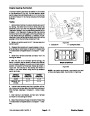


7.
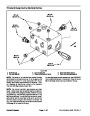
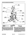
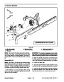
of input gear case.
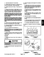
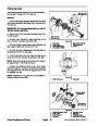
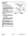
Remove hydraulic hose from hydraulic fitting on side
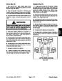
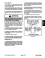
8. Install wheels to axle. Lower machine to ground.
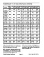
Torque wheel lug nuts from 85 to 100 ft--lb (116 to 135
N--m).
8.
9.
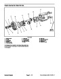
Remove lock nut and flat washer from axle pivot pin.
Support rear axle to prevent it from falling. Remove
9.
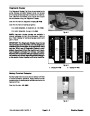
Fill axle with SAE 85W--140 weight gear lube.
pivot pin. Lower rear axle from machine. Note location
of thrust washer on both ends of axle mounting boss.
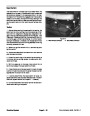
10.Check rearwheeltoe--inandadjustifnecessary(see
Traction Unit Operator’s Manual).
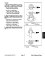
10.If
ing cylinder from axle (see Steering Cylinder in Service
and Repairs section of Chapter 4 -- Hydraulic System).
neededforfurtheraxledisassembly,removesteer-
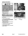
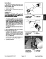
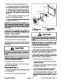
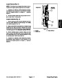
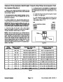
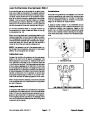
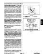
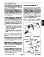
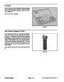
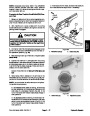
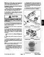
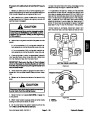
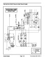
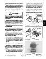
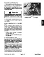
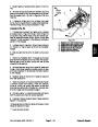
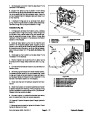
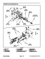
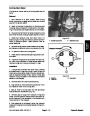
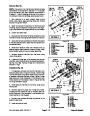
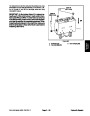
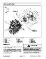
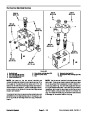
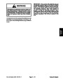
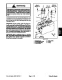
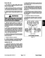
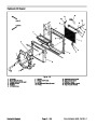
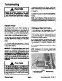
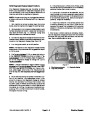
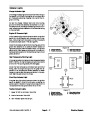
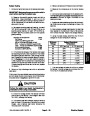
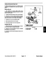
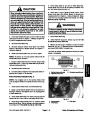
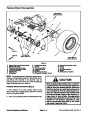
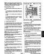
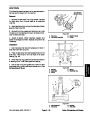
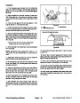
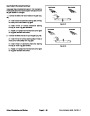
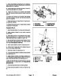
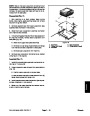
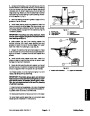
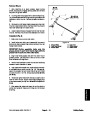
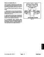
11.Check steering stop bolt adjustment. When the
steering cylinder is fully contracted (left turn), a gap of
1/16” (1.6 mm) should exist between bevel gear case
casting and stop bolt on left axle case. Figure 11 shows
stop bolt location.
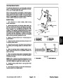
11.
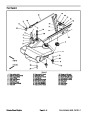
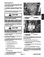
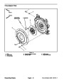
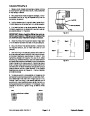
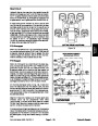
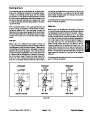
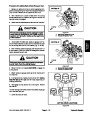
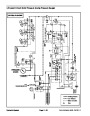
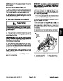
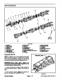
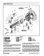
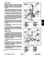
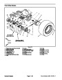
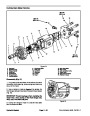
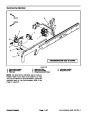
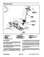
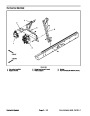
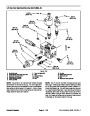
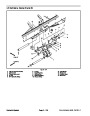
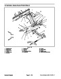
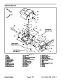
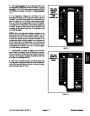
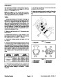
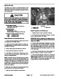
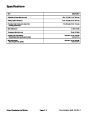
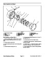
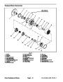
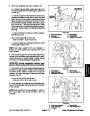
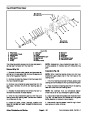
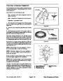
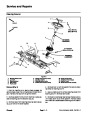
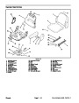
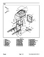
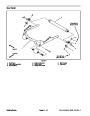
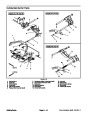
If required, remove tie rod ends from steering arms
on rear axle (Fig. 10). Remove the cotter pins and castle
nuts from the tie rod ball joints. Use a ball joint fork and
remove the tie rod ends from the axle steering arms.
4
3
2
12.Clean
the rear axle pivot pin and pivot bushings. In-
5
spectthepinandbushingsforwearordamage.Replace
components as necessary.
1
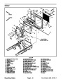
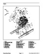
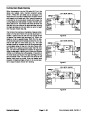
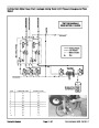
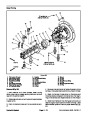
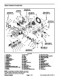
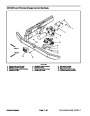
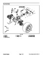
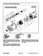
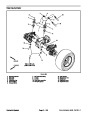
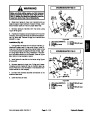
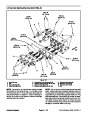
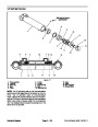
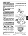
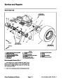
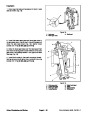
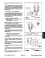
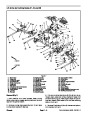
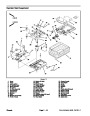
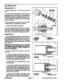
Install Rear Axle (Fig. 9)
6
1.
If removed, install steering cylinder to axle assembly
(seeSteering Cylinder inService andRepairs section of
Chapter 4 -- Hydraulic System).
2.
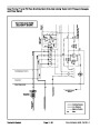
Tighten ball joint castle nuts and install new cotter pins.
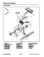
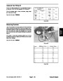
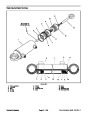
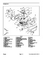
If removed, install the tie rod to rear axle (Fig. 10).
Figure 10
3.
axle assembly to rear frame mount.
Support axle under machine with a jack. Position
1.
2.
3.
Tie rod
Dust cover
Cotter pin
4.
5.
6.
Castle nut
Tie rod end
Steering arm (LH)
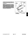
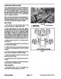
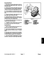
4.
Install axle pivot pin to secure axle to frame. Make
sure to install thrust washer between axle pivot and
frame on both ends of the pivot. With washers installed,
there should be from 0.002 to 0.020 inch (0.05 to 0.51
mm) clearance between rear frame mount and axle
mounting boss. Add thrust washers if needed to adjust
clearance.
1
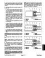
5.
Lock nut should be tightened enough to allow pivot pin
Install flat washer and lock nut onto axle pivot pin.
to rotate (70 ft--lb (94 N--m) maximum).
6.
Axle Motor in Service and Repairs section of Chapter 4
Install hydraulic motor to axle assembly (see Rear
--
Hydraulic System).
2
7.
gear case.
Install hydraulic hoses to steering cylinder and input
Figure 11
1.
Steering stop bolt
2.
Bevel gear case (LH)
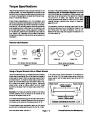
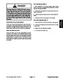
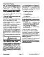
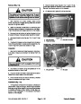
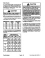
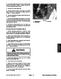
WARNING
Failure to maintain proper wheel lug nut torque
could result in failure or loss of wheel and may
result in personal injury.
Groundsmaster 4500--D/4700--D
Page 6 -- 15
Axles, Planetaries and Brakes
| Categories | Lawn Mower Manual, Sprinkler and Irrigation Manuals, Toro Sprinkler and Irrigation Manuals |
|---|---|
| Tags | Toro Groundsmaster 30857, Toro Groundsmaster 30858, Toro Groundsmaster 4500 D, Toro Groundsmaster 4700 D |
| Download File |
|
| Document Type | Service Manual |
| Language | English |
| Product Brand | Toro. Customer Service Representatives are available by phone:
Monday - Friday 7:30 a.m. to 9:00 p.m. (CDT) - Saturday 8:00 a.m. to 8:00 p.m. (CDT) - Sunday 10:00 a.m. to 8:00 p.m. (CDT)
Canada 1-888-225-4886 USA 1-888-384-9939, Lawn Mower |
| Document File Type | |
| Publisher | toro.com |
| Wikipedia's Page | Toro Company |
| Copyright | Attribution Non-commercial |
(0 votes, average: 0 out of 5)