


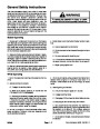


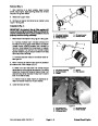


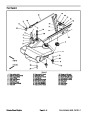
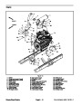
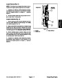


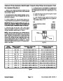
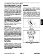


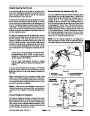


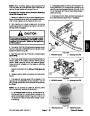
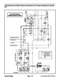
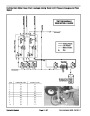
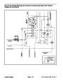
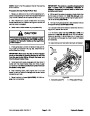


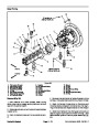
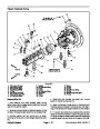
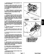

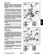

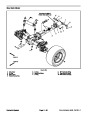
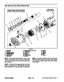

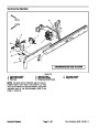
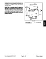


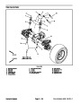
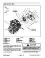

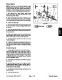
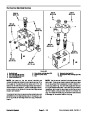

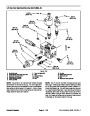


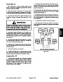
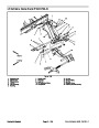
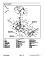
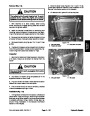


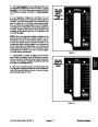
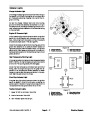
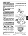
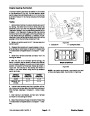
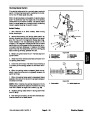


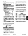


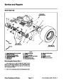

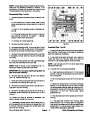


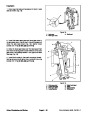
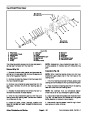
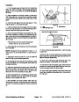
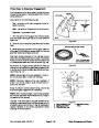


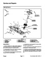
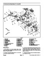


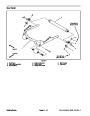
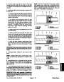


Removal (Fig. 103)
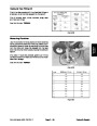
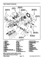
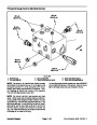
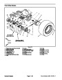
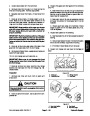
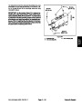
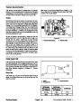
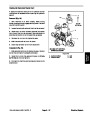
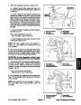
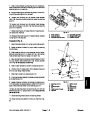
1. If fittings were removed from junction manifold, lubri-
cate and place new O--rings onto fittings. Install fittings
into manifold openings making sure that orifice is cor-
rectlyplacedbeforethreadingfittingintomanifold.Tight-
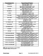
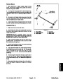
en fittings (see Hydraulic Fitting Installation in the
General Information section of this chapter). Refer to
Figure 104 for fitting installation torque.
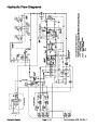
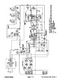
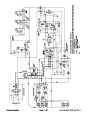
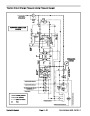
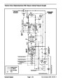
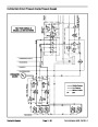
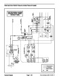
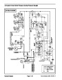
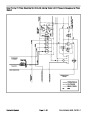
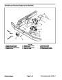
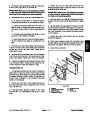
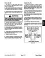
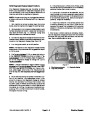
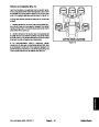
NOTE: The ports on the lift circuit junction manifold are
marked for easy identification of components (e.g. P1 is
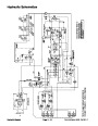
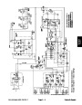
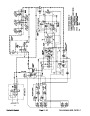
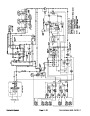
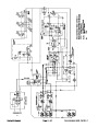
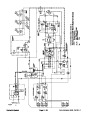
the gear pump connection port). See Hydraulic Sche-
matics in Chapter 9 -- Foldout Drawings to identify the
function of the hydraulic lines at each port.
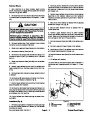
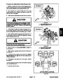
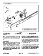
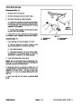
1.
decks, stop engine, engage parking brake and remove
key from the ignition switch.
Park machine on a level surface, lower cutting
2.
103
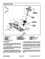
Install hydraulic manifold to the frame using Figure
as guide.
3.
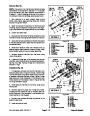
Remove caps and plugs from fittings and hoses.
2.
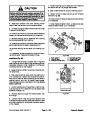
Installing Hydraulic System Components at the begin-
ning of the Service and Repairs section of this chapter.
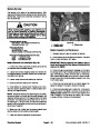
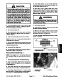
Read the General Precautions for Removing and
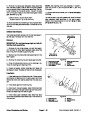
Properly connect hydraulic lines to manifold (see Hy-
draulic Hose and Tube Installation in the General Infor-
mation section of this chapter).
3.
manifold removal, thoroughly clean exterior ofmanifold.
To prevent contamination of hydraulic system during
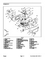
20
(27.1
ft--lb
N--m)
5
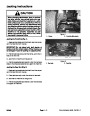
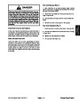
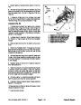
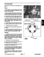
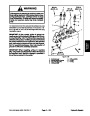
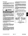
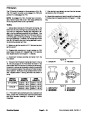
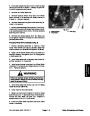
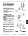
WARNING
2
3
Make sure that cutting decks are fully lowered
before loosening hydraulic lines from lift circuit
junction manifold. If decks are raised as hydrau-
lic lines are loosened, decks may drop unexpect-
edly.
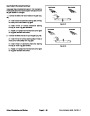
UP
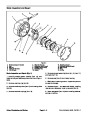
4.
caps or plugs on open hydraulic lines and fittings. Label
disconnected hydraulic lines for proper assembly.
Disconnect hydraulic lines from manifold and put
1
3
5.
Remove hydraulic manifold from the frame using
Figure 103 as guide.
4
25
ft--lb
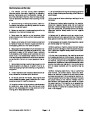
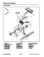
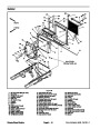
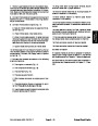
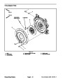
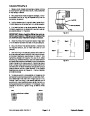
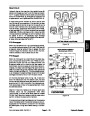
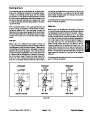
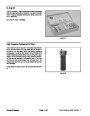
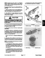
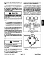
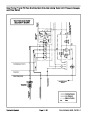
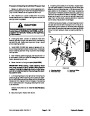
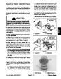
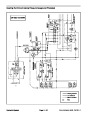
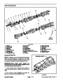
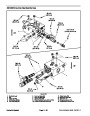
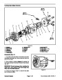
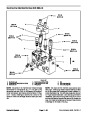
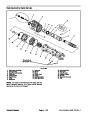
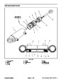
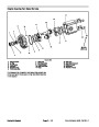
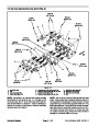
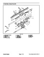
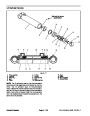
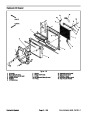
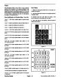
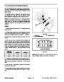
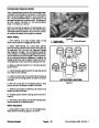
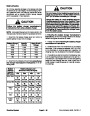
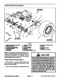
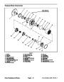
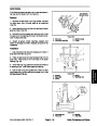
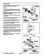
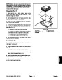
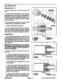
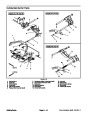
IMPORTANT: A flow control orifice is placed be-
neath several of the hydraulic fittings on the lift cir-
cuit junction manifold (Fig. 104). The manifold uses
two (2) different orifice sizes. If a fitting is removed
from the lift junction manifold and an orifice is in the
manifoldport,makesuretoremoveorifice andlabel
its position for assembly purposes. Also note loca-
tion of groove in orifice for assembly purposes.
(33.9 N--m)
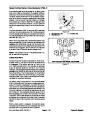
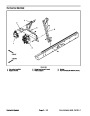
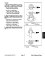
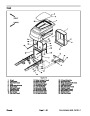
Figure 104
1.
2.
3.
Manifold body
Orifice (0.055)
Orifice (0.030)
4.
5.
Straight fitting (3 used)
Zero leak plug
6.
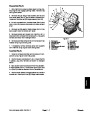
If necessary, remove fittings from manifold and dis-
card O--rings (Fig. 104).
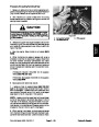
Installation (Fig. 103)
IMPORTANT: When installing orifice in manifold,
make sure that orifice is flat in the base of the man-
ifold port. Manifold damage is possible if the orifice
is cocked in the cavity.
Groundsmaster 4500--D/4700--D
Page 4 -- 125
Hydraulic System
| Categories | Lawn Mower Manual, Sprinkler and Irrigation Manuals, Toro Sprinkler and Irrigation Manuals |
|---|---|
| Tags | Toro Groundsmaster 30857, Toro Groundsmaster 30858, Toro Groundsmaster 4500 D, Toro Groundsmaster 4700 D |
| Download File |
|
| Document Type | Service Manual |
| Language | English |
| Product Brand | Toro. Customer Service Representatives are available by phone:
Monday - Friday 7:30 a.m. to 9:00 p.m. (CDT) - Saturday 8:00 a.m. to 8:00 p.m. (CDT) - Sunday 10:00 a.m. to 8:00 p.m. (CDT)
Canada 1-888-225-4886 USA 1-888-384-9939, Lawn Mower |
| Document File Type | |
| Publisher | toro.com |
| Wikipedia's Page | Toro Company |
| Copyright | Attribution Non-commercial |
(0 votes, average: 0 out of 5)