


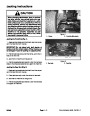


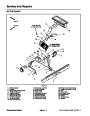


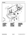
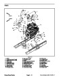
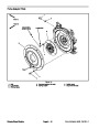


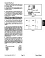
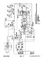
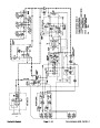


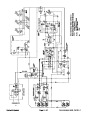

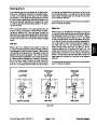

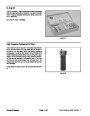
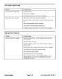
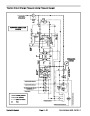


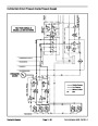
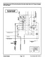
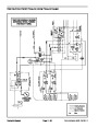
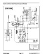
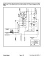


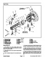
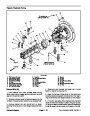

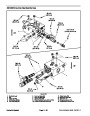

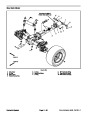
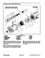

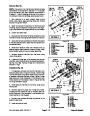
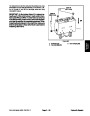

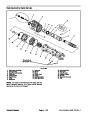

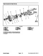

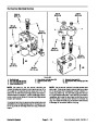

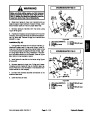


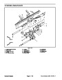
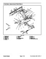
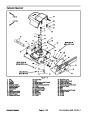


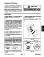
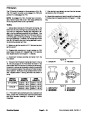
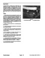


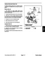


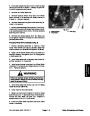
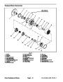


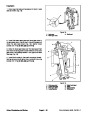
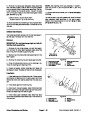
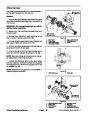
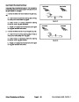


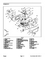


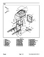


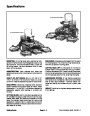


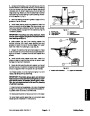
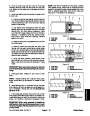


Removal (Fig. 10)
Park machine on a level surface, lower cutting
decks, stop engine, engage parking brake and remove
key from the ignition switch.
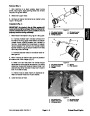
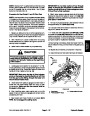
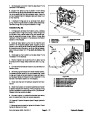
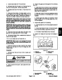
7. After assembly, raise and lower the cutting deck to
verify that hydraulic hoses and fittings do not contact
anything.
1.
2.
Operator’s Manual).
Remove cutting deck from lift arm (see Cutting Deck
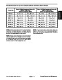
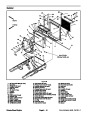
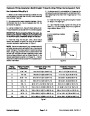
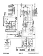
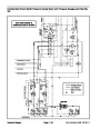
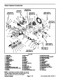
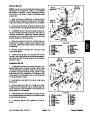
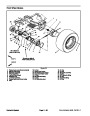
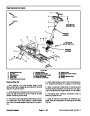
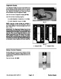
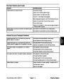
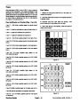
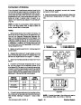
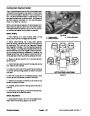
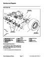
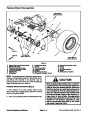
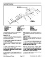
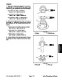
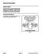
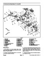
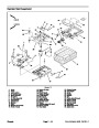
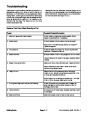
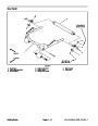
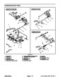
#4
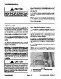
Deck
#1 Deck
#5 Deck
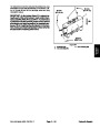
3.
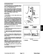
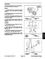
Remove lift cylinder pin (item 10) that secures liftcyl-
inder to lift arm.
4.
5.
and frame. Locate and remove thrust washer (item 14)
from rear of lift arm during pivot pin removal.
Loosen and remove lock nut (item 17) from pivot pin.
Support lift arm and pull lift arm pivot pin from lift arm
#
2
#3
Deck
#
6 Deck
#7 Deck
(GM4700)
Deck
(GM4700)
6.
7.
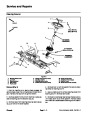
Remove lift arm from machine.
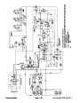
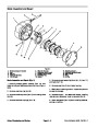
Disassemble lift arm as needed using Figure 10 as
a guide.
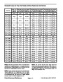
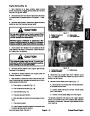
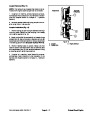
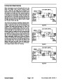
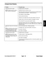
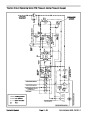
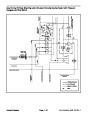
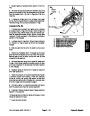
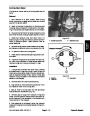
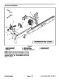
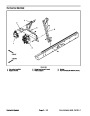
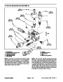
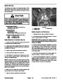
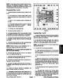
CUTTING DECK LOCATIONS
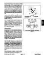
8.
and pivot pin for damage or wear.Replace worn or dam-
aged components.
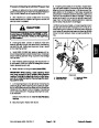
Clean lift arm and pivot pin. Inspect lift arm bushings
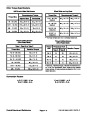
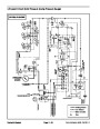
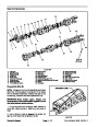
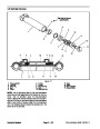
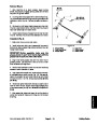
Figure 11
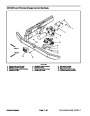
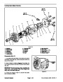
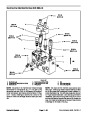
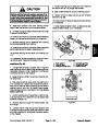
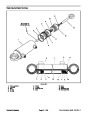
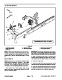
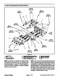
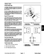
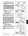
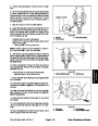
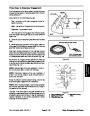
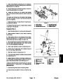
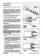
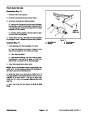
Installation (Fig. 10)
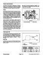
1.
Assemble lift arm using Figure 7 as a guide.
2.
Position lift arm to frame (Fig. 10). Fit thrust washer
(item 14) between rear of lift arm and frame. Slide pivot
pin into frame and lift arm. Align roll pin in pivot pin with
slot in frame flange.
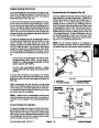
3.
Install and tighten lock nut (item 17) to secure lift arm
pivot pin.
4.
10).
Secure lift cylinder to lift arm with cylinder pin (item
Secure cylinder pin to lift arm with flange head
screw and flange nut.
NOTE: Install thrust washer on deck pivot shaft before
installing cutting deck on pivot shaft.
5.
Position and install cutting deck to lift arm (see Cut-
ting Deck Operator’s Manual).
NOTE: The lift arms for cutting decks #2 and #3 are
fitted with a lift arm rotation stop block (item 3). This stop
istokeep thedeck stable while raised.Toadjustrotation
stop,remove two(2)setscrews from stop and fully raise
cutting deck to position the stop. Apply Loctite #242 (or
equivalent) to set screws and install set screws to se-
cure stop. The rotation stop should contact the lift arm
across the full width of the stop.
6.
Lubricate lift arm and lift cylinder grease fittings after
assembly is complete.
Groundsmaster 4500--D/4700--D
Page 7 -- 11
Chassis
| Categories | Lawn Mower Manual, Sprinkler and Irrigation Manuals, Toro Sprinkler and Irrigation Manuals |
|---|---|
| Tags | Toro Groundsmaster 30857, Toro Groundsmaster 30858, Toro Groundsmaster 4500 D, Toro Groundsmaster 4700 D |
| Download File |
|
| Document Type | Service Manual |
| Language | English |
| Product Brand | Toro. Customer Service Representatives are available by phone:
Monday - Friday 7:30 a.m. to 9:00 p.m. (CDT) - Saturday 8:00 a.m. to 8:00 p.m. (CDT) - Sunday 10:00 a.m. to 8:00 p.m. (CDT)
Canada 1-888-225-4886 USA 1-888-384-9939, Lawn Mower |
| Document File Type | |
| Publisher | toro.com |
| Wikipedia's Page | Toro Company |
| Copyright | Attribution Non-commercial |
(0 votes, average: 0 out of 5)