


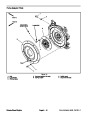


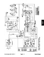
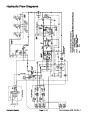
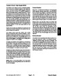


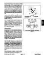


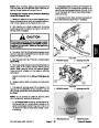
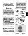
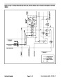


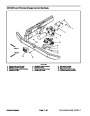
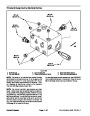


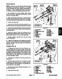
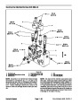


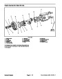

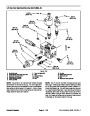
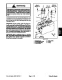


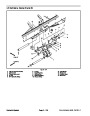
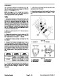
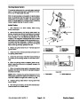


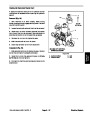
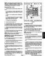


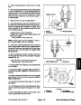
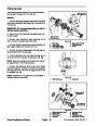


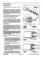


Steering Circuit
A four section gear pump is coupled to the piston (trac-
tion) pump. The gear pump section P3 supplies hydrau-
lic flow to the steering control valve and the lift/lower
controlvalve.Pumphydraulicflowisdeliveredtothetwo
circuits through a proportional flow divider located in the
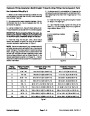
fan control manifold. Steering circuit pressure is limited
to1050PSI(72bar)byareliefvalve locatedinthesteer-
ing control valve.
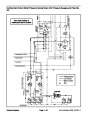
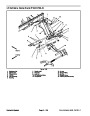
the cylinder is proportional to the amount of the turning
on the steering wheel. Fluid leaving the cylinder flows
backthroughthespoolvalvethenthroughtheTportand
to the hydraulic reservoir.
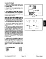
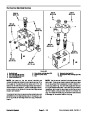
The steering control valve returns to the neutral position
when turning is completed.
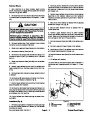
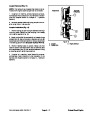
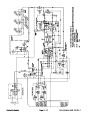
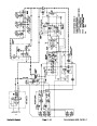
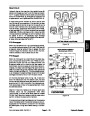
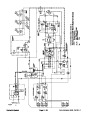
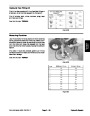
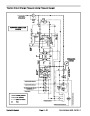
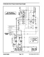
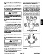
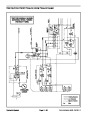
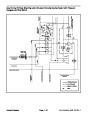
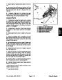
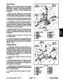
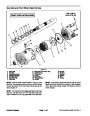
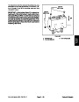
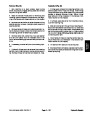
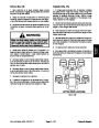
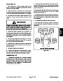
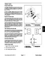
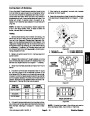
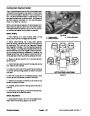
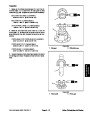
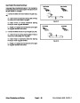
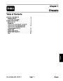
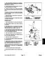
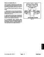
Right Turn
With the steering wheel in the neutral position and the
engine running, pump section P3 flow enters the steer-
ing control valve at the P port and goes through the
steering control spool valve, bypassing the rotary meter
(V1) and steering cylinder.Flow leaves the control valve
through the PB port to the oil filter and traction charge
circuit.
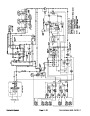
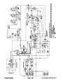
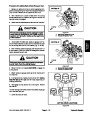
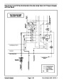
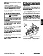
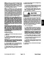
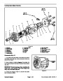
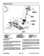
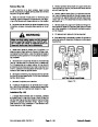
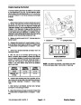
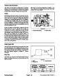
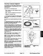
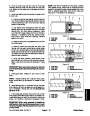
When a right turn is made with the engine running, the
turningofthesteeringwheelpositionsthespoolvalveso
that flow goes through the bottom of the spool. Flow en-
tering the steering control valve at the P port goes
through the spool and is routed to two places. As in aleft
turn, most of the flow through the valve is bypassed out
the PB port back to the oil filter and traction charge cir-
cuit. Also like a left turn, the remainder of the flow is
drawn through rotary meter (V1) but goes out port R.
Pressure extends the lift cylinder for a right turn. The
rotary meter ensures that the oil flow to the cylinder is
proportional to the amount of the turning on the steering
wheel. Fluid leaving the cylinder flows back through the
spool valve then through the T port and to the hydraulic
reservoir.
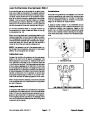
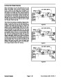
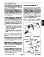
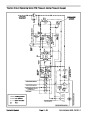
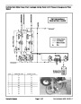
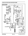
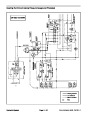
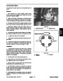
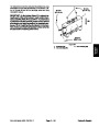
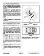
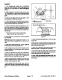
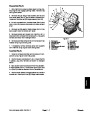
Left Turn
When a left turn is made with the engine running, the
turningofthesteeringwheelpositionsthespoolvalveso
thatflowgoesthroughthetopofthespool.Flowentering
the steering control valve at the P port goes through the
spool and is routed to two places. First, most of the flow
throughthevalveisbypassedoutthePBportbacktothe
oil filter and traction charge circuit. Second, the remain-
der of the flow is drawn through the rotary meter (V1)
and out the L port. Pressure contracts the lift cylinder for
a left turn. The rotary meter ensures that the oil flow to
The steering control valve returns to the neutral position
when turning is completed.
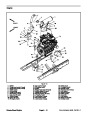
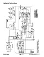
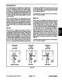
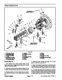
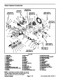
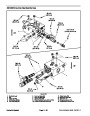
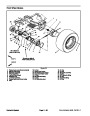
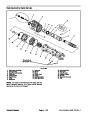
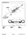
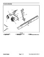
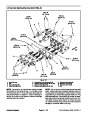
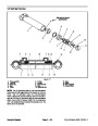
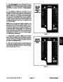
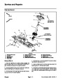
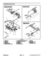
STEERING CYLINDER
STEERING CYLINDER
PISTON MOVEMENT
STEERING CYLINDER
NO PISTON MOVEMENT
PISTON MOVEMENT
R
L
R
L
R
L
1
050
1050
1050
PSI
PSI
PSI
T
PB
P
T
PB
P
T
PB
P
STEERING
CONTROL
VALVE
STEERING
CONTROL
VALVE
STEERING
CONTROL
VALVE
NEUTRAL POSITION
LEFT TURN
RIGHT TURN
Figure 23
Groundsmaster 4500--D/4700--D
Page 4 -- 29
Hydraulic System
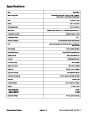
| Categories | Lawn Mower Manual, Sprinkler and Irrigation Manuals, Toro Sprinkler and Irrigation Manuals |
|---|---|
| Tags | Toro Groundsmaster 30857, Toro Groundsmaster 30858, Toro Groundsmaster 4500 D, Toro Groundsmaster 4700 D |
| Download File |
|
| Document Type | Service Manual |
| Language | English |
| Product Brand | Toro. Customer Service Representatives are available by phone:
Monday - Friday 7:30 a.m. to 9:00 p.m. (CDT) - Saturday 8:00 a.m. to 8:00 p.m. (CDT) - Sunday 10:00 a.m. to 8:00 p.m. (CDT)
Canada 1-888-225-4886 USA 1-888-384-9939, Lawn Mower |
| Document File Type | |
| Publisher | toro.com |
| Wikipedia's Page | Toro Company |
| Copyright | Attribution Non-commercial |
(0 votes, average: 0 out of 5)