


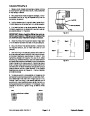


5.
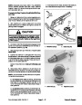
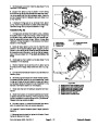
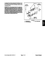
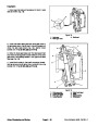
Brake cable end should be completely threaded onto
pull rod before tightening jam nut.
Install brake cable to pull rod on brake assembly.
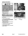
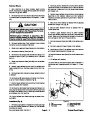
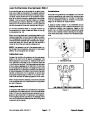
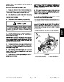
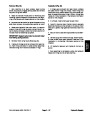
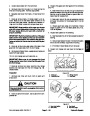
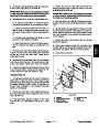
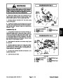
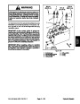
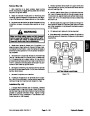
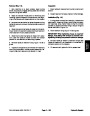
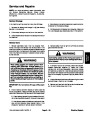
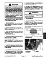
CAUTION
6.
Install new o--ring on hydraulic wheel motor. Install
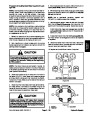
When changing attachments, tires or perform-
ingotherservice,use correct blocks, hoistsand
jacks to raise and support machine. Make sure
machine is parked on a solid level surface such
as a concrete floor. Prior to raising machine, re-
move any attachments that may interfere with
the safe and proper raising of the machine. Al-
ways chock or block wheels. Use appropriate
jack stands to support the raised machine. If the
machine is not properly supported by jack
stands, the machine may move or fall, which
may result in personal injury.
wheel motor (see Front Wheel Motors in Service and
RepairssectionofChapter4 -- HydraulicSystem).Make
sure that mounting cap screws are torqued from 75 to
85
ft--lb (102 to 115 N--m).
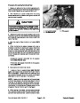
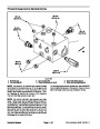
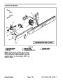
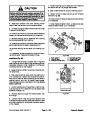
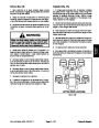
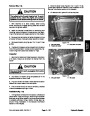
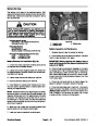
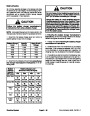
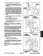
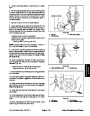
WARNING
Failure to maintain proper wheel lug nut torque
could result in failure or loss of wheel and may
result in personal injury.
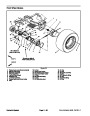
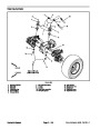
3.
Chock rear wheels and jack up front of machine (see
7. Install wheel assembly.
JackingInstructions inChapter1 -- Safety).Supportma-
chine with appropriate jack stands.
8.
to 100 ft--lb (116 to 135 N--m).
Lower machine to ground. Torque lug nuts from 85
4.
Remove wheel assembly.
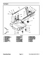
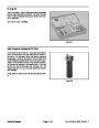
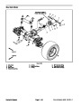
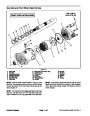
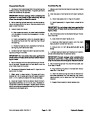
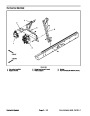
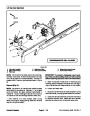
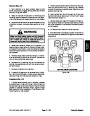
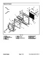
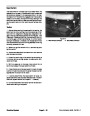
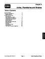
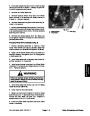
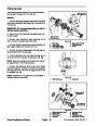
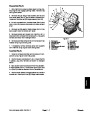
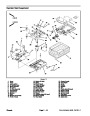
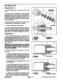
9.
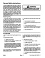
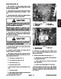
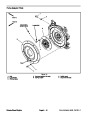
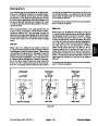
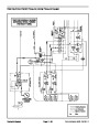
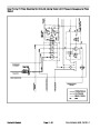
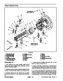
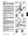
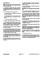
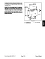
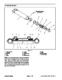
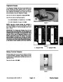
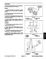
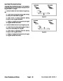
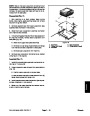
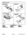
Make sure drain plug is installed in bottom of brake
5.
Motors in Service and Repairs section of Chapter 4 --
Hydraulic System).
Remove hydraulic wheel motor (see Front Wheel
assembly (Fig. 3). Fill planetary wheel drive/brake as-
sembly with SAE 85W--140 gear lube.
10.Check
for proper brake operation and adjust brake
6.
Disconnect brake cable from pull rod on brake.
cables if necessary.
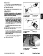
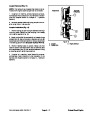
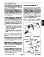
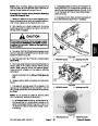
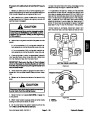
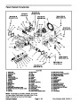
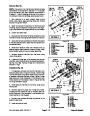
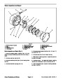
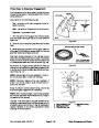
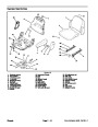
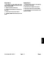
NOTE: Be careful to not drop splined brake shaft as
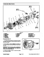
brake assembly is removed.
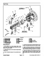
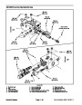
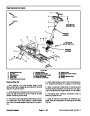
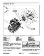
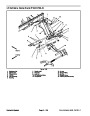
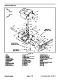
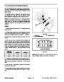
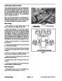
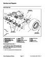
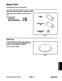
3
2
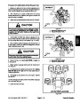
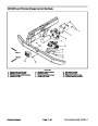
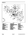
7.
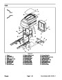
cap screws (item 11) securing brake assembly to frame.
Remove brake assembly.
Support brake assembly and remove flange head
1
8.
9.
Remove splined brake shaft.
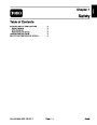
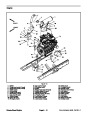
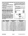
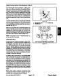
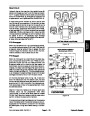
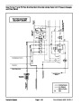
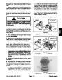
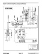
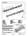
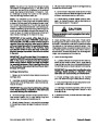
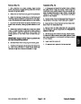
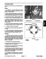
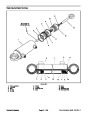
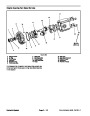
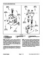
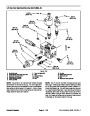
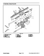
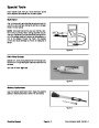
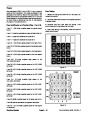
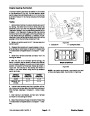
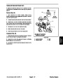
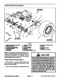
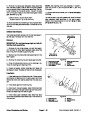
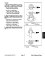
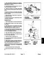
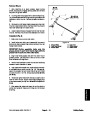
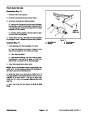
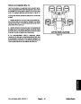
Figure 2
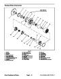
Complete brake inspection and repair (see Brake In-
1.
2.
Splined brake shaft step
3.
Planetary assembly end
spection and Repair in this section).
Hydraulic motor end
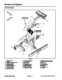
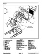
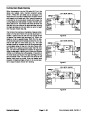
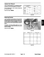
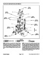
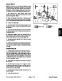
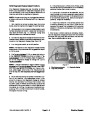
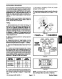
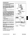
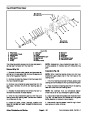
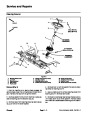
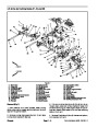
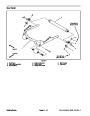
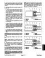
Brake Assembly Installation (Fig. 1)
NOTE: The stepped end of the splined brake shaft
must be aligned toward the hydraulic wheel motor (Fig.
2).
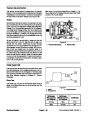
1
1.
Install splined brake shaft into brake assembly.
2
2.
Apply Loctite Gasket Sealant #2 (or equivalent) to
sealing surfaces of new gasket (item 19). Apply gasket
to brake assembly.
3
3.
Install brake assembly onto frame, aligning splined
brake shaft with input shaft on planetary wheel drive.
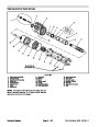
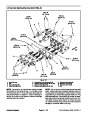
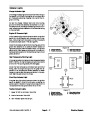
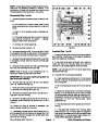
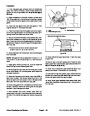
Figure 3
4.
assembly to frame. Tighten screws in a crossing pattern
Install flange head screws (item 11) to secure brake
1.
2.
Brake housing
Check plug
3.
Drain plug
to a torque from 75 to 85 ft--lb (102 to 115 N--m).
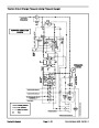
Groundsmaster 4500--D/4700--D
Page 6 -- 5
Axles, Planetaries and Brakes
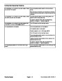
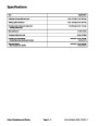
| Categories | Lawn Mower Manual, Sprinkler and Irrigation Manuals, Toro Sprinkler and Irrigation Manuals |
|---|---|
| Tags | Toro Groundsmaster 30857, Toro Groundsmaster 30858, Toro Groundsmaster 4500 D, Toro Groundsmaster 4700 D |
| Download File |
|
| Document Type | Service Manual |
| Language | English |
| Product Brand | Toro. Customer Service Representatives are available by phone:
Monday - Friday 7:30 a.m. to 9:00 p.m. (CDT) - Saturday 8:00 a.m. to 8:00 p.m. (CDT) - Sunday 10:00 a.m. to 8:00 p.m. (CDT)
Canada 1-888-225-4886 USA 1-888-384-9939, Lawn Mower |
| Document File Type | |
| Publisher | toro.com |
| Wikipedia's Page | Toro Company |
| Copyright | Attribution Non-commercial |
(0 votes, average: 0 out of 5)