
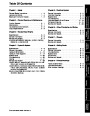


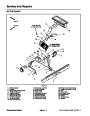


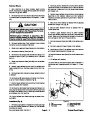
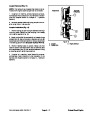


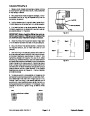
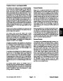
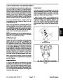


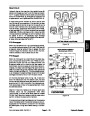

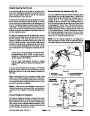


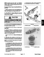
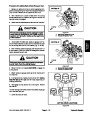
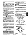
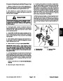
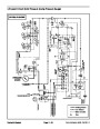
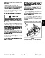


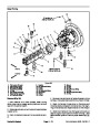
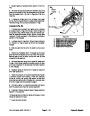
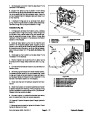
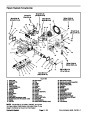

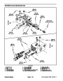

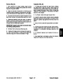
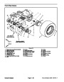
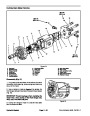

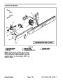

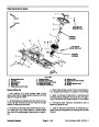

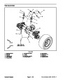
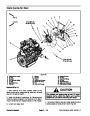

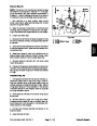

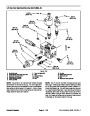


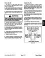
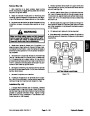


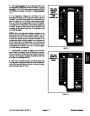
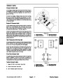
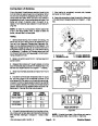
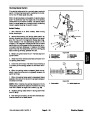


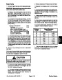


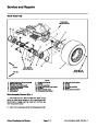

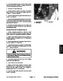


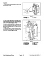
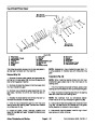
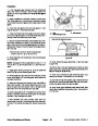


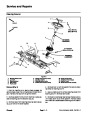
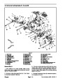


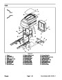


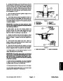
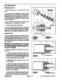


Removal (Fig. 64)
4
75 ft--lb
25
33.9 N--m)
ft--lb
(101
N--m)
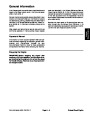
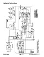
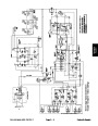
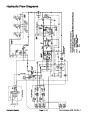
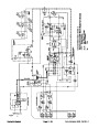
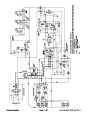
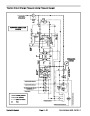
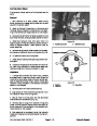
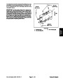
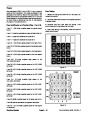
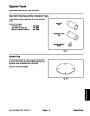
NOTE: The ports on the manifolds are marked for easy
identification of components. Refer to the Hydraulic
Schematics in Chapter 9 -- Foldout Drawings to identify
the function of the hydraulic lines and cartridge valves
at each port.
9
(
8
2
6
7
5
5
10
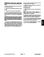
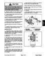
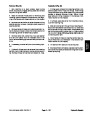
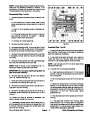
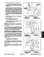
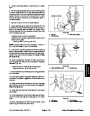
1.
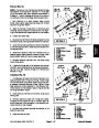
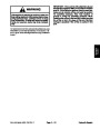
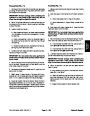
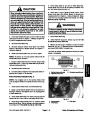
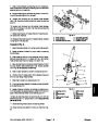
Installing Hydraulic System Components at the begin-
ning of the Service and Repairs section of this chapter.
Read the General Precautions for Removing and
5
(68
0 ft--lb
N--m)
6
11
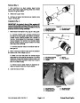
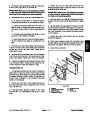
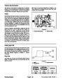
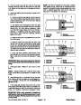
2.
manifold removal, thoroughly clean exterior ofmanifold.
To prevent contamination of hydraulic system during
2
12
4
3.
If 4WD/2WD control manifold is being removed, la-
15
bel wire harness electrical connectors that attach to
manifold components. Disconnect harness electrical
connectors from the solenoid valve coil and electrical
sensors (pressure and temperature).
4
3
2
13
2
(27.1
0 ft--lb
N--m)
1
14
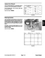
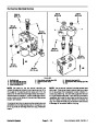
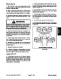
4.
Disconnect hydraulic lines from manifold being re-
moved and put caps or plugs on open hydraulic lines
andfittings. Labeldisconnected hydraulic lines forprop-
er assembly.
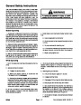
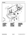
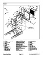
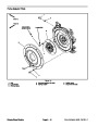
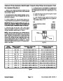
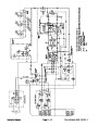
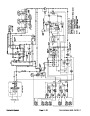
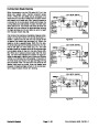
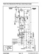
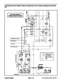
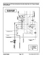
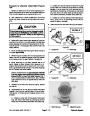
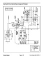
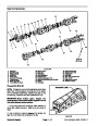
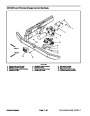
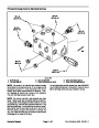
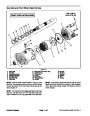
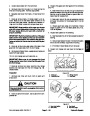
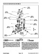
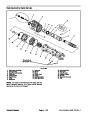
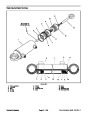
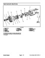
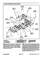
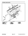
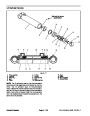
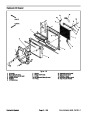
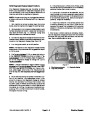
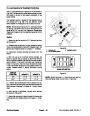
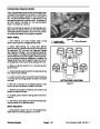
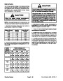
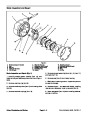
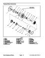
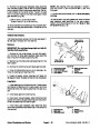
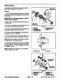
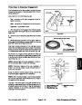
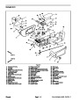
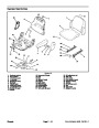
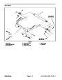
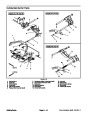
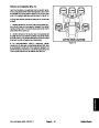
Figure 65
1.
2.
3.
4.
5.
6.
7.
8.
4WD/2WD manifold
9.
Check fitting
O--ring
10. O--ring
45o fitting
11. O--ring
O--ring
12. Straight fitting
13. O--ring
5.
Remove hydraulic manifold from the frame using
90o fitting
Figure 64 as guide.
Straight fitting
O--ring
14. Test fitting
15. Dust cap
6.
If hydraulic fittings are to be removed from control
O--ring
manifold,markfittingorientation toallowcorrectassem-
bly (Figure 65 or 66). Remove fittings from manifold and
discard O--rings.
25
(33.9
ft--lb
N--m)
50
(68 N--m)
ft--lb
6
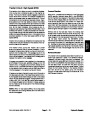
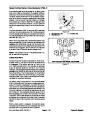
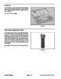
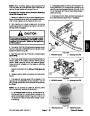
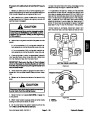
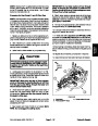
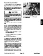
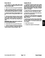
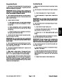
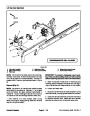
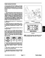
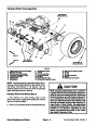
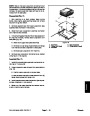
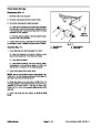
Installation (Fig. 64)
20
(27.1
ft--lb
N--m)
5
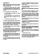
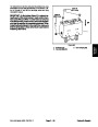
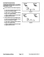
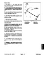
1.
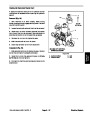
If fittings were removed from control manifold, lubri-
7
4
cate and place new O--rings onto fittings. Install fittings
into manifold ports using marks made during theremov-
al process to properly orientate fittings. Tighten fittings
(see Hydraulic Fitting Installation in the General Infor-
mation section of this chapter). Refer to Figure 65 or 66
for fitting installation torque.
4
8
11 10
9
2
3
1
17
12
8
2.
64
Install hydraulic manifold to the frame using Figure
as guide.
3.
Remove caps and plugs from fittings and hoses.
4
Properly connect hydraulic lines to manifold (see Hy-
draulic Hose and Tube Installation in the General Infor-
mation section of this chapter).
14
15
13
16
8
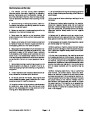
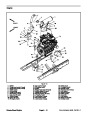
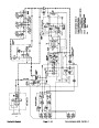
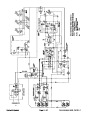
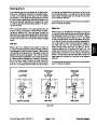
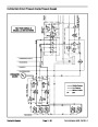
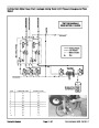
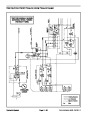
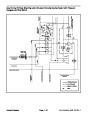
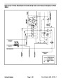
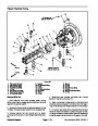
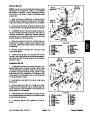
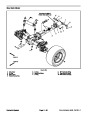
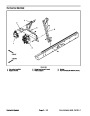
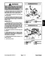
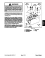
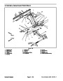
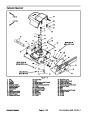
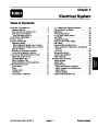
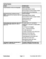
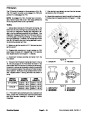
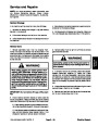
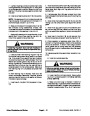
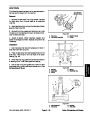
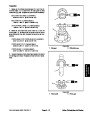
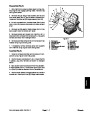
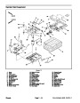
Figure 66
4.
wire harness electrical connectors to the solenoid valve
coil and electrical sensors.
If4WD/2WD control manifoldwasremoved,connect
1.
Filtration manifold
10. 90o fitting
11. O--ring
2.
3.
4.
5.
6.
7.
8.
9.
O--ring
90o fitting
O--ring
Straight fitting
O--ring
Straight fitting
O--ring
O--ring
12. Test fitting
13. Dust cap
14. Tee fitting
5.
quired.
Fill hydraulic reservoir with hydraulic fluid as re-
15. O--ring
16. 90o fitting
17. O--ring
Groundsmaster 4500--D/4700--D
Page 4 -- 81
Hydraulic System
| Categories | Lawn Mower Manual, Sprinkler and Irrigation Manuals, Toro Sprinkler and Irrigation Manuals |
|---|---|
| Tags | Toro Groundsmaster 30857, Toro Groundsmaster 30858, Toro Groundsmaster 4500 D, Toro Groundsmaster 4700 D |
| Download File |
|
| Document Type | Service Manual |
| Language | English |
| Product Brand | Toro. Customer Service Representatives are available by phone:
Monday - Friday 7:30 a.m. to 9:00 p.m. (CDT) - Saturday 8:00 a.m. to 8:00 p.m. (CDT) - Sunday 10:00 a.m. to 8:00 p.m. (CDT)
Canada 1-888-225-4886 USA 1-888-384-9939, Lawn Mower |
| Document File Type | |
| Publisher | toro.com |
| Wikipedia's Page | Toro Company |
| Copyright | Attribution Non-commercial |
(0 votes, average: 0 out of 5)